
Multifunctional mobile power supply equipment
A mobile power supply, multi-functional technology, applied in transducer circuits, current collectors, electric vehicles, etc., can solve problems such as single function, poor safety, and inability to monitor online, and achieve the effect of reducing environmental pollution
- Summary
- Abstract
- Description
- Claims
- Application Information
AI Technical Summary
Problems solved by technology
Method used
Image

Examples
Embodiment 1
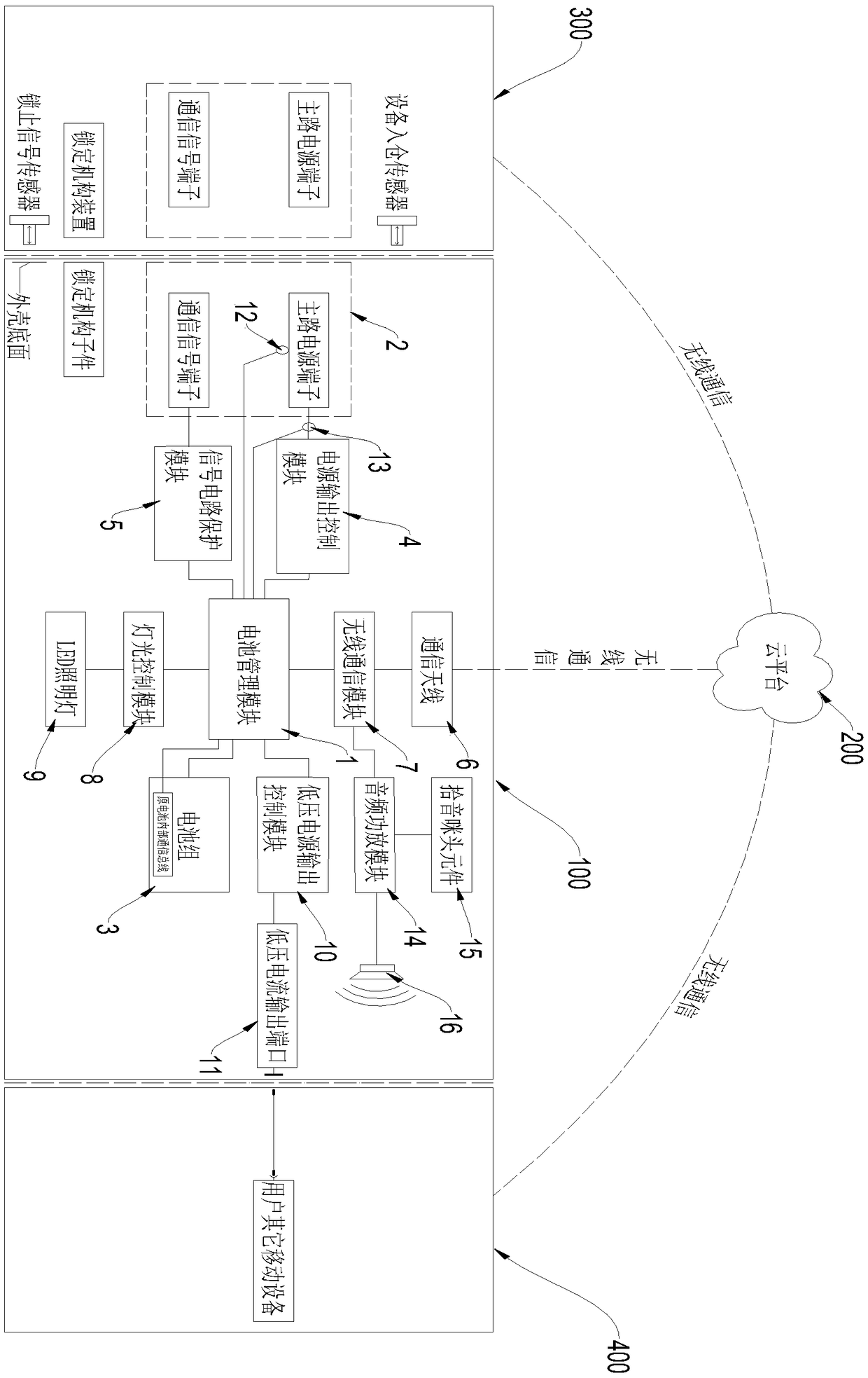
[0024] Such as figure 1 As shown, the multifunctional mobile power supply device 100 includes a battery management module 1, a connector 2, a battery pack 3, a power output control module 4, a signal circuit protection module 5, a communication antenna 6, a wireless communication module 7, a lighting control module 8 and LED lighting lamp 9, wherein the battery management module 1 is electrically connected to the battery pack 3, the battery management module 1 is electrically connected to the main power supply terminal of the connector 2 through the power output control module 4, and the battery management module 1 is electrically connected to the signal circuit protection module 5 It is electrically connected to the communication signal terminal of the connector 2, the wireless communication module 7 is electrically connected to the communication antenna 6 and the battery management module 1, and the lighting control module 8 is electrically connected to the LED lighting 9 and...
Embodiment 2
[0032] This embodiment is based on Embodiment 1, and the difference between this embodiment and Embodiment 1 is that the multifunctional mobile power supply device 100 in this embodiment also includes an audio power amplifier module 14, a microphone head element 15 and a speaker 16 , the audio power amplifier module 14 is electrically connected to the microphone head element 15, the speaker 16, the battery management module and the wireless communication module respectively. During use, the user terminal is connected to the multifunctional mobile power supply device 100 through the wireless communication module 7, and when the audio APP software on the user terminal performs audio playback, the user terminal outputs a high-fidelity audio signal and sends it to the audio power amplifier through the wireless communication module 7 The module 14 is used to amplify the power of the audio power amplifier module 14, and finally output the audio sound wave through the speaker 16. Whe...
Embodiment 3
[0035] This embodiment is based on Embodiment 2. The difference between this embodiment and Embodiment 2 is that the multifunctional mobile power device 100 in this embodiment also includes a temperature sensor 12 and a current sensing module 13. The temperature sensor 12 and the The battery management module 1 is electrically connected, and the current sensing module 13 is electrically connected to the battery management module 1 . The temperature sensor 12 is arranged on the terminal of the main power supply, and the temperature sensor 12 is used to collect temperature information on the terminal of the main power supply and convert it into an electrical signal and send it to the battery management module 1 . When the battery management module 1 receives the temperature information sent by the temperature sensor 12, it compares it with the pre-stored temperature upper limit and lower limit threshold. When the temperature measured by the temperature sensor 12 exceeds the tempe...
PUM
 Abstract
Description
Claims
Application Information