Anti-icing system and anti-icing control method of inlet lip of engine

A control method and technology of anti-icing system, applied in the direction of machine/engine, mechanical equipment, jet propulsion device, etc., can solve the problems of affecting flight safety, reducing air intake area, damaging engine fan blades, etc., and reducing the skin temperature. , The effect of reducing the amount of bleed air and preventing insufficient heating

Active Publication Date: 2015-04-22
COMAC +1
View PDF4 Cites 1 Cited by
  • Summary
  • Abstract
  • Description
  • Claims
  • Application Information

AI Technical Summary

Problems solved by technology

The icing of the intake port will reduce the effective intake area of ​​the engine intake port, which may cause the engine thrust to drop and surge. Icing off may damage the engine fan blades, and seriously cause the engine to stall, affecting flight safety.

Method used


Image

  • Anti-icing system and anti-icing control method of inlet lip of engine
  • Anti-icing system and anti-icing control method of inlet lip of engine

Examples


Embodiment Construction

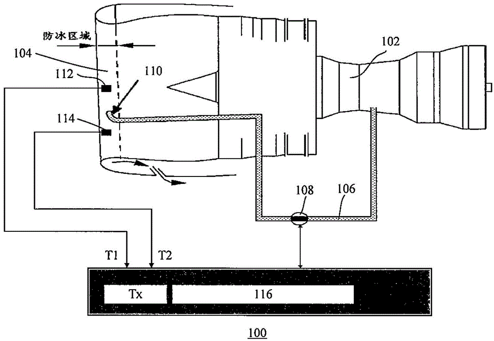
[0024] Such as figure 1 As shown, there is shown an anti-icing system 100 for an intake lip of an engine. The anti-icing system 100 includes a high-pressure compressor 102 , an air inlet 104 , an air induction pipe 106 , a pressure regulation shut-off valve 108 , a swirl nozzle 110 , a first temperature sensor 112 , a second temperature sensor 114 and a controller 116 .

[0025] Specifically, the air inlet end of the air induction pipe 106 is connected to a certain stage of the high-pressure compressor 102 to introduce the hot gas of the high-pressure compressor 102, and the swirl nozzle 110 at its outlet end is arranged on the lip of the air inlet 104 The annular cavity is used to release hot gas so as to prevent ice from forming on the lip of the air intake duct 104 .

[0026] A pressure regulating shut-off valve 108 is arranged on the air induction pipe 106 for adjusting the flow rate of the hot gas in the air induction pipe 106 .

[0027] The first temperature sensor 112...


PUM


Abstract

The invention relates to an anti-icing system of an inlet lip of an engine. The system comprises an air guiding tube, a pressure adjusting shut-off valve, a first temperature sensor, a second first temperature sensor and a controller, wherein an air inlet of the air guiding tube is connected on a high-pressure compressor to lead-in hot air of the high-pressure compressor while an air outlet of the air guiding tube is formed in a circular chamber of the inlet lip to release the hot air; the pressure adjusting shut-off valve is distributed on the air guiding tube and is used for adjusting the flow of the hot air in the air guiding tube; the first temperature sensor is distributed in a predetermined hottest region of the inlet lip of the engine; the second temperature sensor is distributed in a predetermined coldest region of the inlet lip of the engine; and the controller is electrically connected with the first temperature sensor, the second temperature sensor and the pressure adjusting shut-off valve and can be used for adjusting the openness of the pressure adjusting shut-off valve according to the temperature T1 sensed by the first temperature sensor and the temperature T2 sensed by the second temperature sensor, so that a covering of the inlet lip is not damaged and is not frozen by the temperature of the inlet lip.

Description

technical field [0001] The invention relates to an anti-icing system and an anti-icing control method for an engine intake port lip. Background technique [0002] When the aircraft is flying in icy weather conditions, icing may occur, especially the engine inlet is more likely to freeze under the action of engine suction. The icing of the air intake will reduce the effective air intake area of ​​the engine air intake, which may cause the engine thrust to drop and surge. Ice falling off may damage the engine fan blades, and seriously cause the engine to stall, affecting flight safety. At present, the engine inlets of civil aircraft are anti-icing with hot gas. According to the distribution method of hot gas inside the engine inlet, the anti-icing of the engine inlets of civil aircraft in service can be divided into flute tube configuration and swirl nozzle configuration. [0003] The representative model of the flute tube configuration is the B737. In this configuration, the...

Claims


Application Information

Patent Timeline
Patent Type & Authority Patents(China)
IPC IPC(8): F02C7/047F02C7/057
Inventor 沈东史献林李志茂王大伟李革萍
Owner COMAC
Why Eureka
Try Eureka