
B-mode ultrasound examination instrument for obstetrics and gynecology department
A technology of obstetrics and gynecology and B-ultrasound, which is applied in the fields of medical equipment, medical science, ultrasound/sonic wave/infrasonic wave diagnosis, etc., can solve problems such as prolonging detection time, reducing detection time and simple operation, etc., so as to improve efficiency, The effect of reducing labor intensity
- Summary
- Abstract
- Description
- Claims
- Application Information
AI Technical Summary
Problems solved by technology
Method used
Image

Examples
Embodiment Construction
[0020] In order to make the technical means, creative features, goals and effects achieved by the present invention easy to understand, the present invention will be further described below in conjunction with specific illustrations.
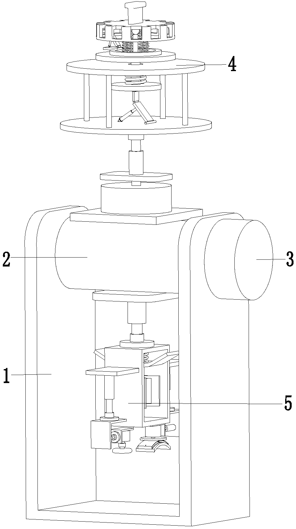
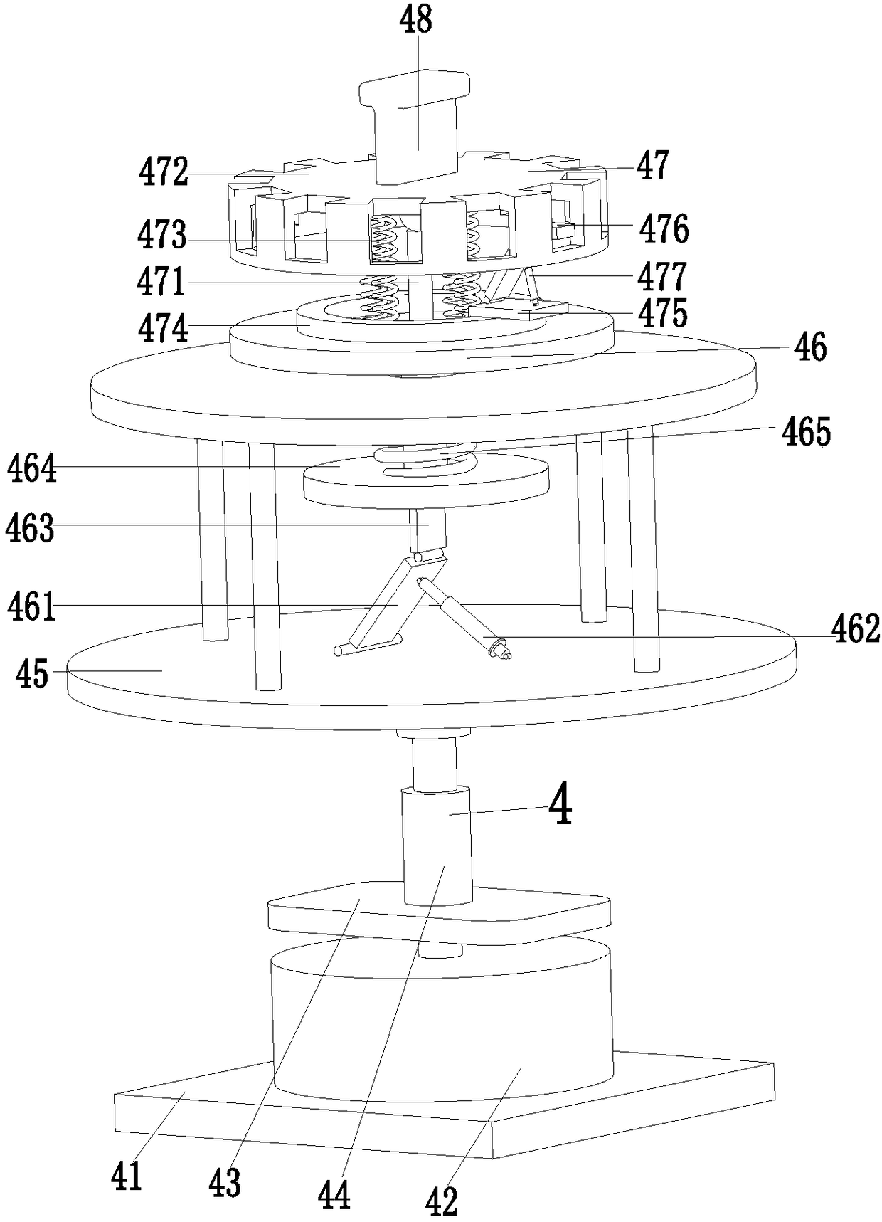
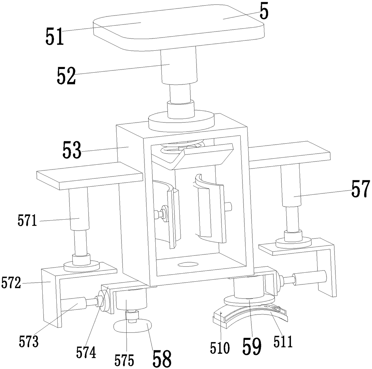
[0021] Such as Figure 1 to Figure 5 As shown, a B-ultrasound examination instrument in obstetrics and gynecology includes a working frame 1, a conversion roller 2 is installed between the inner walls of the working frame 1 through bearings, and the right end of the conversion roller 2 is connected to the output shaft of the conversion motor 3 through a coupling , the conversion motor 3 is installed on the outer wall of the work frame 1 through the motor base, the upper end of the conversion roller 2 is equipped with a working device 4, and the lower end of the conversion roller 2 is installed with a coating device 5, and the conversion motor 3 can control the coating device 5 and the operation The device 4 performs movement adjustment to ensure t...
PUM
 Abstract
Description
Claims
Application Information