Articulated self-propelled raise-boring machine

A raise drilling rig, self-propelled technology, applied in rotary drilling rig, impact drilling, rotary drilling and other directions, can solve the problems of affecting drilling accuracy, high requirements for underground tunnels, large turning radius, etc. Hole accuracy, improve ground passability, and reduce the effect of turning radius

Pending Publication Date: 2018-10-19
湖南一二矿山科技有限公司
View PDF0 Cites 6 Cited by
  • Summary
  • Abstract
  • Description
  • Claims
  • Application Information

AI Technical Summary

Problems solved by technology

The structural characteristics of traditional raise drilling rigs require a lot of manpower and time in the process of equipment transfer and transportation, which brings a lot of inconvenience to the site construction
[0003] In order to solve the walking problem of the raise drilling rig, the current domestic method is to integrate the working host and power unit of the raising drilling rig on the mobile chassis. Although this technology effectively solves the walking problem of the raising drilling rig, the raising drilling rig with this structure The size of the whole machine is relatively large, the turning radius is large, and the requirements for underground roadways are high, so it is difficult to adapt to the walking requirements of small and medium-sized mine roadways in China.
In addition, this mobile large-aperture patio drilling rig rigidly connects the main machine, mobile chassis, and power unit. When drilling in a vertical position, factors such as the weight and vibration of the mobile chassis and power unit will affect the stability of the main machine structure. And then affect the drilling accuracy

Method used


Image

  • Articulated self-propelled raise-boring machine
  • Articulated self-propelled raise-boring machine
  • Articulated self-propelled raise-boring machine

Examples


Embodiment Construction

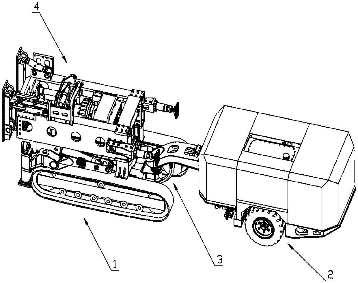
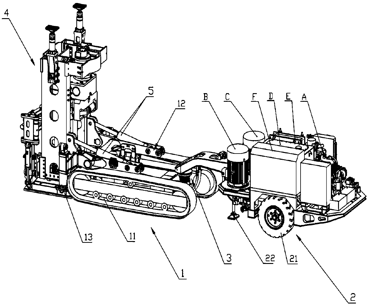
[0037] Such as figure 1 , figure 2 As shown, the articulated self-propelled raise drilling rig provided in this embodiment includes a front frame 1 , a rear frame 2 , a floating hinge mechanism 3 and a main engine assembly 4 .

[0038] The front frame 1 includes a crawler chassis 11 , a floating frame 12 and a front leg 13 .

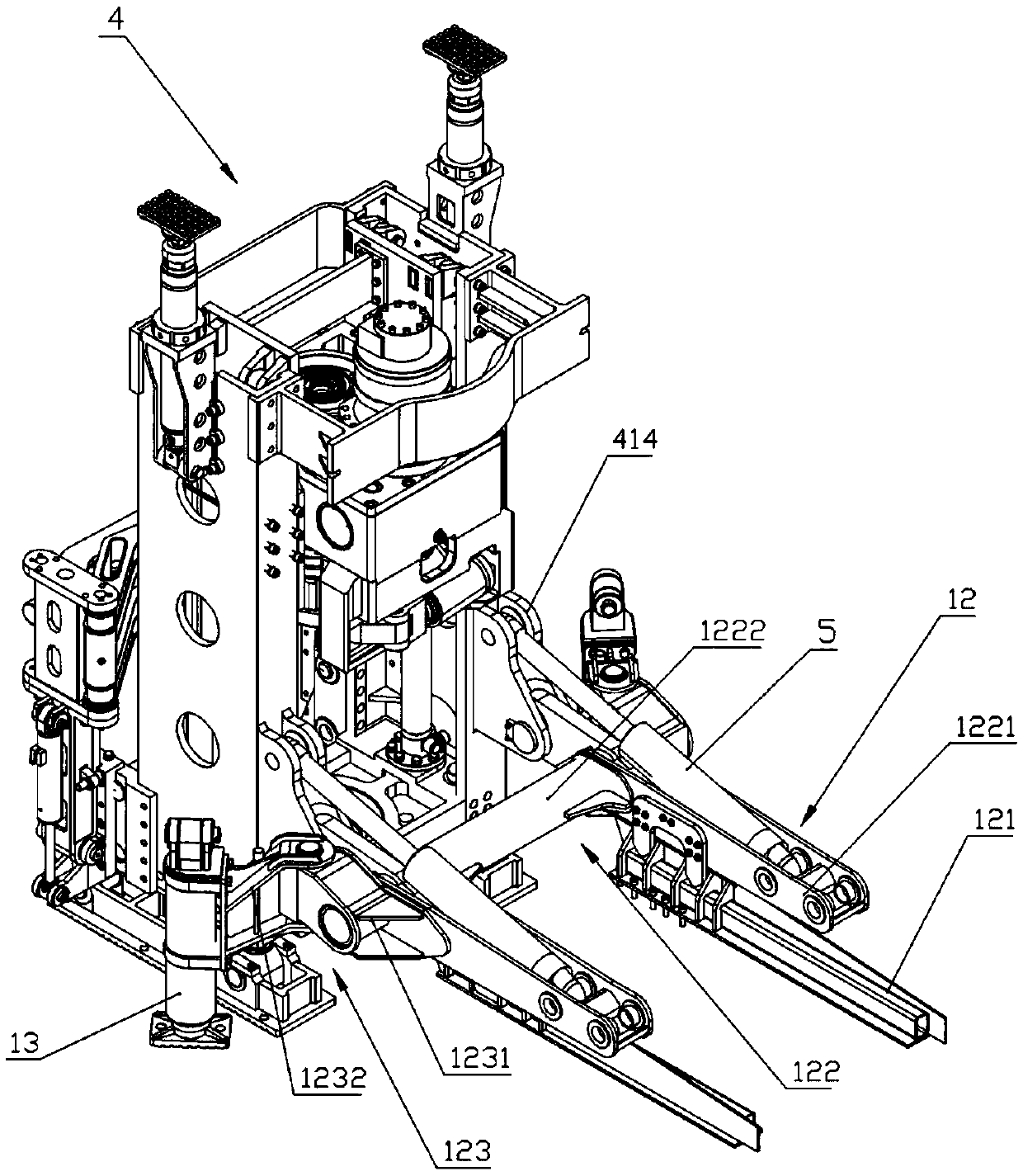
[0039] Such as image 3 , Figure 4As shown, the floating frame 12 includes a base frame 121 , a suspension beam frame 122 and a leg mounting assembly 123 . Underframe 121 has a pair, is symmetrically arranged on it with respect to the center plane of the width direction of crawler chassis 11; Suspension beam frame 122 comprises a pair of suspension beams 1221 that are arranged directly above the underframe and the strengthening beam 1222 that connects two suspension beams as a whole, suspension beam It includes a pair of side plates and a center plate; one end of the center plate is provided with a hinge hole, the hinge hole is a long hole, the oth...


PUM


Abstract

The invention discloses an articulated self-propelled raise-boring machine. The articulated self-propelled raise-boring machine comprises a host assembly, a front frame and a rear frame, wherein the front frame comprises a tracked chassis, a floating frame and front supporting legs; the floating frame is assembled on the tracked chassis; a pair of front supporting legs is respectively articulatedto two sides of the floating frame; the rear frame comprises a wheeled chassis; rear supporting legs are arranged below the wheeled chassis; the host assembly is connected with the floating frame, sothat the host assembly is not constrained by the front frame in the vertical direction, further a host is not influenced by factors such as frame weight and vibration in the boring process, and boringprecision is improved; the front frame is connected with the rear frame by a floating hinging mechanism, so that the front frame and the rear frame can horizontally rotate around a center shaft and vertically deflect around the center shaft; turning radius of the boring machine during traveling is reduced, ground trafficability of the boring machine is improved, and the boring machine better adapts to severe environments of narrow underground roadway and uneven road surface; by arrangement of the tracked chassis and the wheeled chassis, the problem of self propelling is solved.

Description

technical field [0001] The invention belongs to the field of mining machinery equipment, in particular to an articulated self-propelled raise drilling machine. Background technique [0002] At present, domestic traditional raise drilling rigs mostly adopt a split structure (that is, the raise drilling rig is divided into two parts: the working host and the power system), and the drilling rig has no independent walking ability. The working host and the power system are transported to the underground separately by cages or underground loaders on the ground. In the middle of the construction, it can be transported to the designated construction site by means of external force traction through the pre-laid track. The structural characteristics of the traditional raise drilling rig require a lot of manpower and time to be invested in the transfer and transportation of the equipment, which brings a lot of inconvenience to the on-site construction. [0003] In order to solve the w...

Claims


Application Information

Patent Timeline
Patent Type & Authority Applications(China)
IPC IPC(8): E21B7/02E21B15/00E21B19/15E21B3/02
CPCE21B7/02E21B3/02E21B7/024E21B15/00E21B19/15
Inventor 龙国强沈盛强黎忠炎
Owner 湖南一二矿山科技有限公司
Why Eureka
Try Eureka