Geotechnical deep-layer compactness sampler

A technology of compaction and sampling machine, which is applied in the fields of basic structure engineering, on-site foundation soil survey, construction, etc. It can solve problems such as difficult operation, unusable, cost exceeding profit, etc., so as to reduce labor intensity and avoid noise interference Effect

Pending Publication Date: 2020-08-14
苏源检测有限公司
View PDF5 Cites 0 Cited by
  • Summary
  • Abstract
  • Description
  • Claims
  • Application Information

AI Technical Summary

Problems solved by technology

[0005] Aiming at the deficiencies of the prior art, the present invention provides a geotechnical deep layer compaction sampling machine, which has the advantages of improving the original state of the soil sample, reducing the difficulty of sampling and lubricating the sampling head at the same time during the operation of the equipment, which solves the existing problem of geotechnical compaction. Sampling is mainly manual drilling, because the current drilling rig generates heat during the rotation of the soil. The solution to the heat is to rely on water circulation to reduce the temperature, and use the equipment without deformation to maintain normal working conditions, but the water changes after entering the borehole. The moisture content of the soil, the soil sample taken out is not in the original state, so it cannot be used; the manual drilling method can be used in shallow layers such as about one meter, but as the depth increases, the soil pressure increases, and the difficulty of soil extraction increases greatly , resulting in low efficiency and cost far exceeding the income, and the required soil samples cannot be taken out because they are disturbed by manual drilling, and the undisturbed soil is taken out. The sampling head of the existing drilling rig needs to use lubricating oil to achieve the effect of lubrication during operation. However, since the sampling head cannot be lubricated when the equipment is running, and most of the existing oil is manually refueled, the operation is difficult

Method used


Image

  • Geotechnical deep-layer compactness sampler
  • Geotechnical deep-layer compactness sampler

Examples


Embodiment Construction

[0022] The following will clearly and completely describe the technical solutions in the embodiments of the present invention with reference to the accompanying drawings in the embodiments of the present invention. Obviously, the described embodiments are only some, not all, embodiments of the present invention. Based on the embodiments of the present invention, all other embodiments obtained by persons of ordinary skill in the art without making creative efforts belong to the protection scope of the present invention.

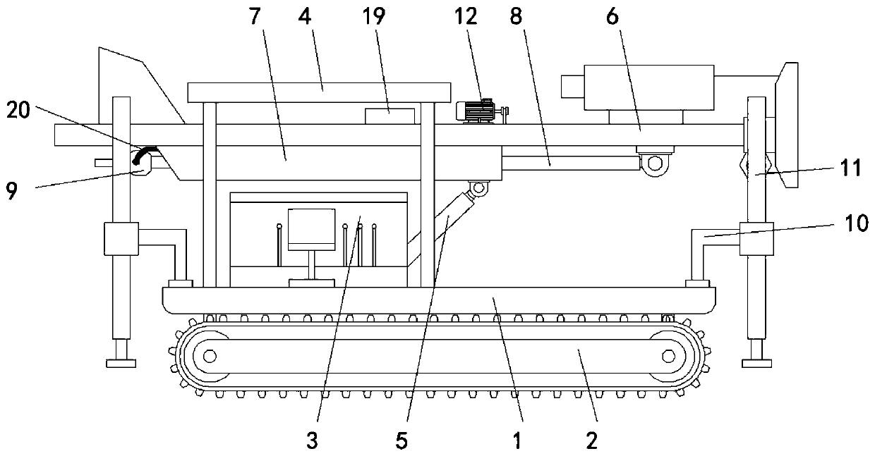
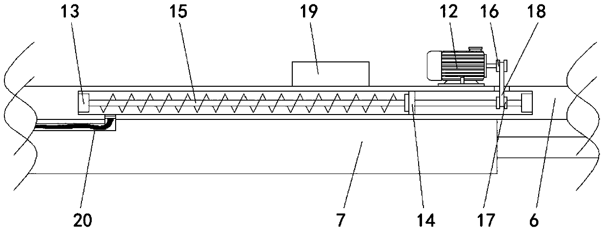
[0023] see Figure 1-2 , geotechnical deep layer compaction sampling machine, including body 1, is characterized in that: the bottom of body 1 is movable to be installed with the crawler belt 2 that quantity is two, and crawler belt 2 is socketed on the outside of the wheel at the bottom of body 1, and the top of body 1 is fixedly installed There is a workbench 3, the top of the vehicle body 1 is fixedly installed with a sunshade 4 on the top of the workbench ...


PUM


Abstract

The invention relates to the technical field of geotechnical sampling, and discloses a geotechnical deep-layer compactness sampler. The geotechnical deep-layer compactness sampler comprises a vehiclebody, two crawlers are movably mounted at the bottom of the vehicle body, a worktable is fixedly mounted at the top of the vehicle body, a sunshade located at the top of the worktable is fixedly mounted at the top of the vehicle body, and a hydraulic supporting column located on the front surface of the worktable is fixedly mounted at the top of the vehicle body. The geotechnical deep-layer compactness sampler drives a first lantern ring to rotate through a conveying belt while rotating through the first lantern ring, thus the first lantern ring drives a spiral conveying rod to rotate after rotating, an oil tank communicates with the interior of a hydraulic cylinder, thus lubricating oil, flowing into the hydraulic cylinder due to the gravity, in the oil tank is conveniently conveyed intoa lubricating oil pipe by the rotated spiral conveying rod, the lubricating oil lubricates a sampling head, and the problem that during operation of traditional equipment, the sampling head cannot belubricated is solved.

Description

technical field [0001] The invention relates to the technical field of geotechnical sampling, in particular to a geotechnical deep layer compaction sampling machine. Background technique [0002] Geotechnical sampling refers to the technical operation of obtaining samples for geotechnical tests. Deep-layer qualitative soil samples are usually drilled with auger drills, spoon drills, sampling tubes or pumping tubes, etc., and undisturbed soil samples should be used with undisturbed samplers. Sampling will cause soil sample disturbance. The so-called undisturbed soil sample refers to the soil sample that has little disturbance in sampling and will not have a significant impact on the measurement of soil mechanical properties. [0003] The existing geotechnical compaction sampling method is mainly the manual drilling method, because the current drilling rig generates heat during the rotation process, and the solution to the heat generation is to rely on water circulation to red...

Claims


Application Information

Patent Timeline
Patent Type & Authority Applications(China)
IPC IPC(8): E02D1/04
CPCE02D1/04
Inventor 周杰何凯陈香王化芹潘磊
Owner 苏源检测有限公司
Why Eureka
Try Eureka