Illumination device and method for orienting MMG panel

A lighting device and panel technology, applied in optics, nonlinear optics, instruments, etc., can solve problems affecting product quality and achieve good alignment effects

Active Publication Date: 2018-11-13
TCL CHINA STAR OPTOELECTRONICS TECH CO LTD
View PDF11 Cites 5 Cited by
  • Summary
  • Abstract
  • Description
  • Claims
  • Application Information

AI Technical Summary

Problems solved by technology

[0006] However, due to the design differences of different products in MMG, when using the same voltage / UV conditions for alignment, it is impossible to achieve uniform and suitable pretilt angles for different products, resulting in defects such as broken bright spots in the products, which affect the quality of some products

Method used


Image

  • Illumination device and method for orienting MMG panel
  • Illumination device and method for orienting MMG panel
  • Illumination device and method for orienting MMG panel

Examples


Embodiment Construction

[0034] In order to further illustrate the technical means adopted by the present invention and its effects, the following describes in detail in conjunction with preferred embodiments of the present invention and accompanying drawings.

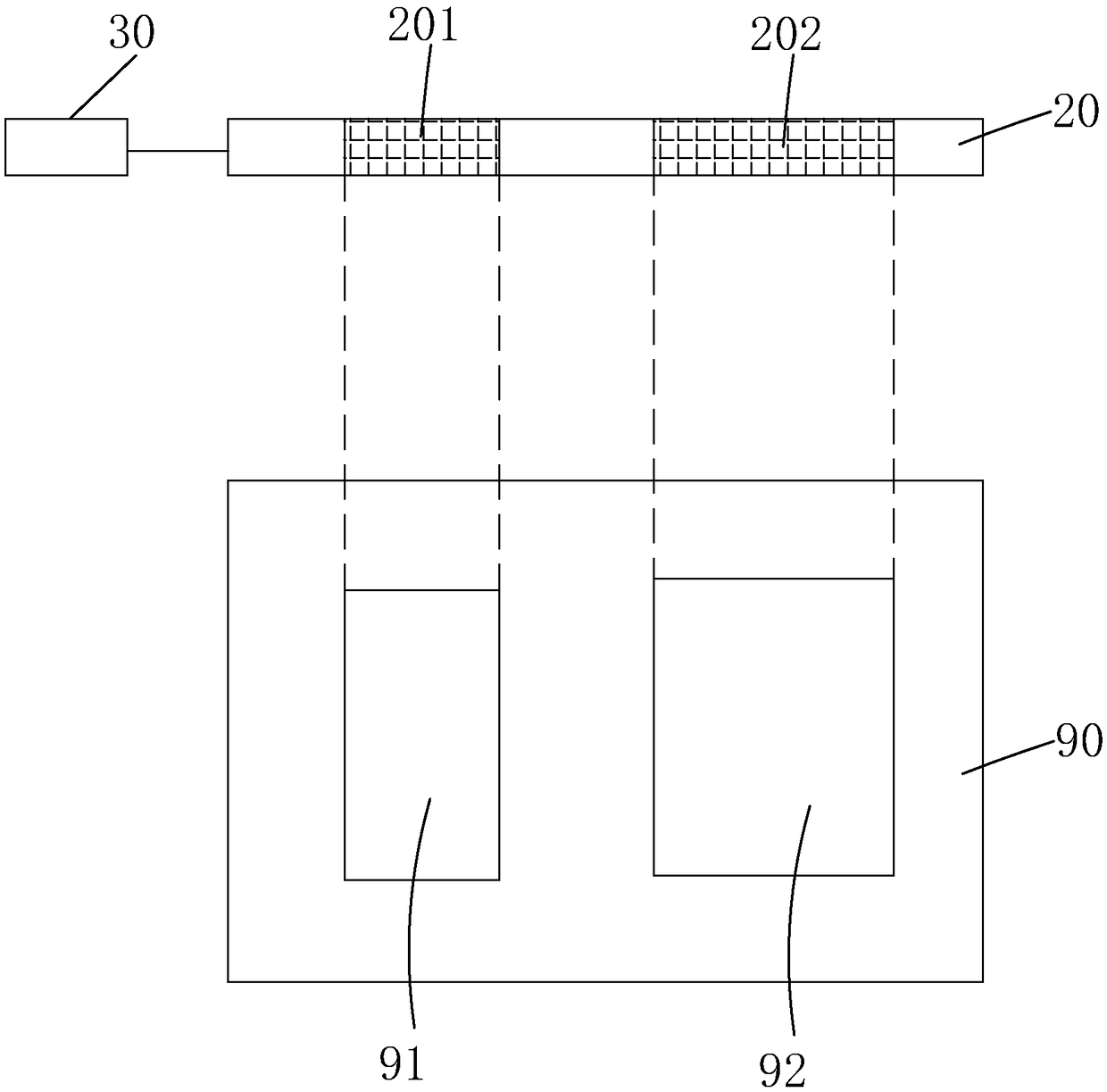
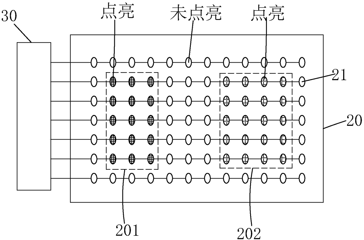
[0035] see figure 1 and figure 2 , the present invention firstly provides a lighting device for aligning the MMG panel 90, including a substrate 10, a plurality of LED point light sources 21 arranged in an array on the substrate 10, and respectively correspondingly covering the plurality of LEDs. Multiple focusing and collimating lens systems 22 on the point light source 21 and a control system 30 electrically connected to the multiple LED point light sources 21 , and the multiple LED point light sources 21 are independently controlled by the control system 30 .

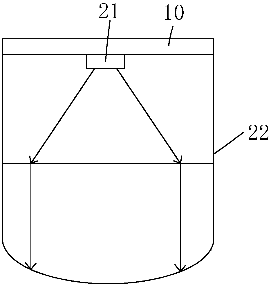
[0036] Such as image 3 As shown, each LED point light source 21 and its corresponding focusing and collimating lens system 22 together form a collimated LED light source, and the...


PUM

PropertyMeasurementUnit
wavelengthaaaaaaaaaa

Abstract

The invention provides an illumination device and a method for orienting an MMG panel. The illumination device is used for orienting the MMG panel, and LED point light sources which are distributed inan array cooperate with a focusing collimating lens system to form a direct type collimation plane light source. In use, the illumination area, the illumination intensity and the illumination time ofthe collimation plane light source can be controlled according to the detailed design of the MMG panel, and a good orienting effect on liquid crystal display panel units with different designs on theMMG panel can be achieved.

Description

technical field [0001] The invention relates to the field of manufacturing liquid crystal displays, in particular to an illumination device and a method for aligning an MMG panel. Background technique [0002] Liquid Crystal Display (LCD) has many advantages such as thin body, power saving, and no radiation, and has been widely used, such as LCD TV, mobile phone, personal digital assistant, digital camera, computer screen or notebook computer screen, etc. . [0003] Most of the existing liquid crystal displays are backlight liquid crystal displays, which include a housing, a liquid crystal panel disposed in the housing, and a backlight module disposed in the housing. Generally, a liquid crystal panel is composed of a color filter substrate (Color Filter, CF), a thin film transistor array substrate (Thin Film Transistor Array Substrate, TFT Array Substrate), and a liquid crystal layer (Liquid Crystal Layer) filled between the two substrates. , its working principle is to co...

Claims


Application Information

Patent Timeline
Patent Type & Authority Applications(China)
IPC IPC(8): G02F1/1337G02F1/13
CPCG02F1/1303G02F1/133788
Inventor 项小群
Owner TCL CHINA STAR OPTOELECTRONICS TECH CO LTD
Why Eureka
Try Eureka