A method of injection molding insert molding

A technology of insert molding and injection mold, applied in coating and other directions, can solve the problems of reducing product production quality, product crushing, mold damage, etc., and achieve the effects of improving injection efficiency and injection quality, reducing damage, and easy demolding

Active Publication Date: 2020-10-09
SUZHOU XIAOYAN AUTOMATION EQUIP
View PDF5 Cites 0 Cited by
  • Summary
  • Abstract
  • Description
  • Claims
  • Application Information

AI Technical Summary

Problems solved by technology

Because the whole process requires manual operation, and there is no monitoring system to effectively monitor the inserts, the mold will be damaged during the installation process, and it may even cause the risk of mold compression! After injection molding, the product and the insert need to be ejected as a whole, and the insert should be disassembled using disassembly tooling. Not only is the operation complicated, but it will also cause crushing and bruising to the product and reduce the production quality of the product.

Method used


Image

  • A method of injection molding insert molding

Examples


Embodiment Construction

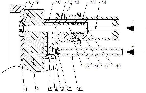
[0026] The technical solutions of the present invention will be described in further detail below in conjunction with the accompanying drawings and specific embodiments.

[0027] Such as figure 1 As shown, 1. Die plate; 2. Support pad; 3. L-shaped connecting seat; 4. Air intake pipe; 5. Air intake nozzle; 6. Feed pipe; 7. Rubber positioning ring; 8. Positioning of embedded parts 9, fastening ring; 10, positioning sleeve; 11, sliding sleeve; 12, second return spring; 13, feeding conduit; 14, ejector rod; 15, second feeding push rod; 16, guide sleeve; 17, the first return spring; 18, clamping plate; 19, orifice plate.

[0028] An injection molding insert molding method, based on an injection molding insert molding equipment, the injection molding insert molding equipment includes: a support pad, the inside of the support pad is provided with a feed channel arranged along the horizontal direction, and one end of the feed channel passes through The positioning ring of the embedd...


PUM


Abstract

The invention relates to an injection moulding insert molding method which is based on an injection moulding insert molding device. The injection moulding insert moulding device comprises a supportingcushion block, an air inlet pipe, a first material pushing mechanism and a second material pushing mechanism. The supporting cushion block is internally provided with a material feeding channel arranged in horizontal direction. One end of the material feeding channel passes through a pre-embedded-part positioning ring, and connected with a pre-embedded-part fixing hole formed in an injection moulding plate. The other end of the material feeding channel is connected with a material feeding duct. The air inlet pipe is vertically arranged. The upper end of the air inlet pipe communicates with the material feeding duct, and the lower end of the air inlet pipe is connected with a high-pressure gas generating device. A pore plate is arranged at the portion, near the bottom end of the air inletpipe, in the air inlet pipe. A material inlet pipe is connected to a side wall, above the pore plate, of the air inlet pipe. A pre-embedded part is placed in the material inlet pipe. The first material pushing mechanism is used for pushing the pre-embedded part entering the material inlet pipe into the air inlet pipe. The second material pushing mechanism is used for sending the pre-embedded partentering the material feeding duct into the pre-embedded part fixing hole formed in the injection moulding plate. The injection molding insert molding method can accurately and quickly realize the accurate placement of an embedded insert on a mould, and the high stability after placement is ensured.

Description

technical field [0001] The invention relates to an injection molding insert molding method. Background technique [0002] At present, there are some insert molding molds on the injection molding site. Inserts need to be installed for production in the process of injection molding products, and the installation of inserts requires manual basic operations---manually install inserts, and during the installation of inserts Manual sliding door operation is required, which not only wastes a lot of manpower input, but also leads to long molding cycle. [0003] According to the structural characteristics of the product, some products need to install multiple inserts during the installation and molding process. During the installation process, the insert product needs to be placed on the manual insert first, and then the insert gland is covered to ensure that the insert product After it will not fall off during the molding process, put the insert filled with the insert product into ...

Claims


Application Information

Patent Timeline
Patent Type & Authority Patents(China)
IPC IPC(8): B29C45/14
CPCB29C45/14008B29C45/14065
Inventor 黄博
Owner SUZHOU XIAOYAN AUTOMATION EQUIP
Why Eureka
Try Eureka