
A basement sewage integrated lifting device
A basement, sewage collection technology, applied in water supply installations, sewage removal, waterway systems, etc., can solve problems such as easy damage and short service life
- Summary
- Abstract
- Description
- Claims
- Application Information
AI Technical Summary
Problems solved by technology
Method used
Image

Examples
Embodiment Construction
[0014] The present invention will be further described below in conjunction with the accompanying drawings of the description.
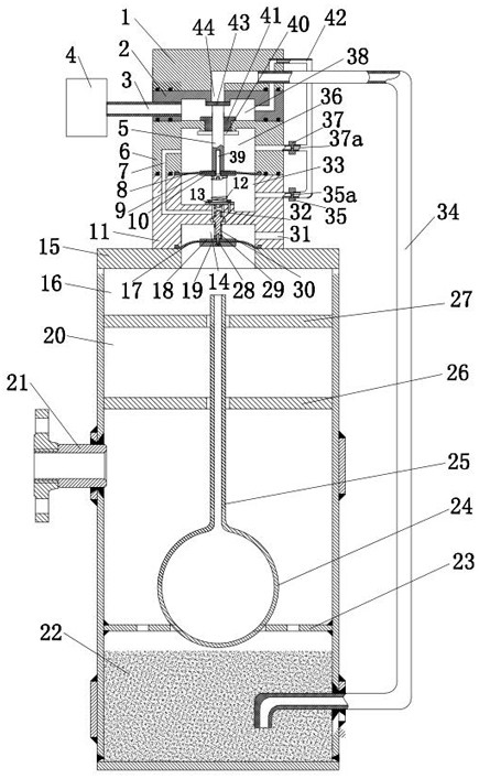
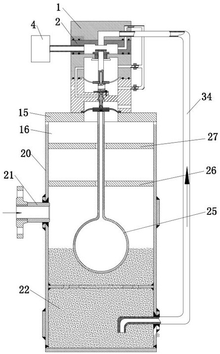
[0015] As shown in the figure, the basement sewage integrated lifting device is composed of a first housing 1, a second housing 2, a third housing 6, a fourth housing 11, a fifth housing 15, and a sewage collector 20. The lower part of the sewage collector 20 is a sewage collection pool 22, the sewage collection pool 22 is connected to the external sewage collection pipe through the sewage collection joint 21, a floating ball 24 is arranged on the sewage collection pool 22, and a push rod 25 is arranged on the floating ball 24, and the fourth shell 11. The fifth elastic diaphragm 17 is arranged between the fifth shell 15 to form the fifth cavity 14 and the sixth cavity 16. The fifth cavity 14 is connected to the first air channel 31, and the fifth elastic diaphragm 17 is fixedly connected to the fifth cavity. The valve rod 30, the upper spring 32 and...
PUM
 Abstract
Description
Claims
Application Information