Microswitch and test system

A technology of micro-switches and sleeves, applied in the direction of electric switches, contacts, electrical components, etc., can solve problems such as unfavorable manufacturing processes

Pending Publication Date: 2019-01-04
LISA DRAXLMAIER GMBH +1
View PDF15 Cites 5 Cited by
  • Summary
  • Abstract
  • Description
  • Claims
  • Application Information

AI Technical Summary

Problems solved by technology

This is disadvantageous in the manufacturing process

Method used


Image

  • Microswitch and test system
  • Microswitch and test system
  • Microswitch and test system

Examples


Embodiment Construction

[0023] The above-mentioned figures are only exemplary diagrams, and are only used to explain the present invention. Identical or functionally identical elements are provided with the same reference numerals throughout.

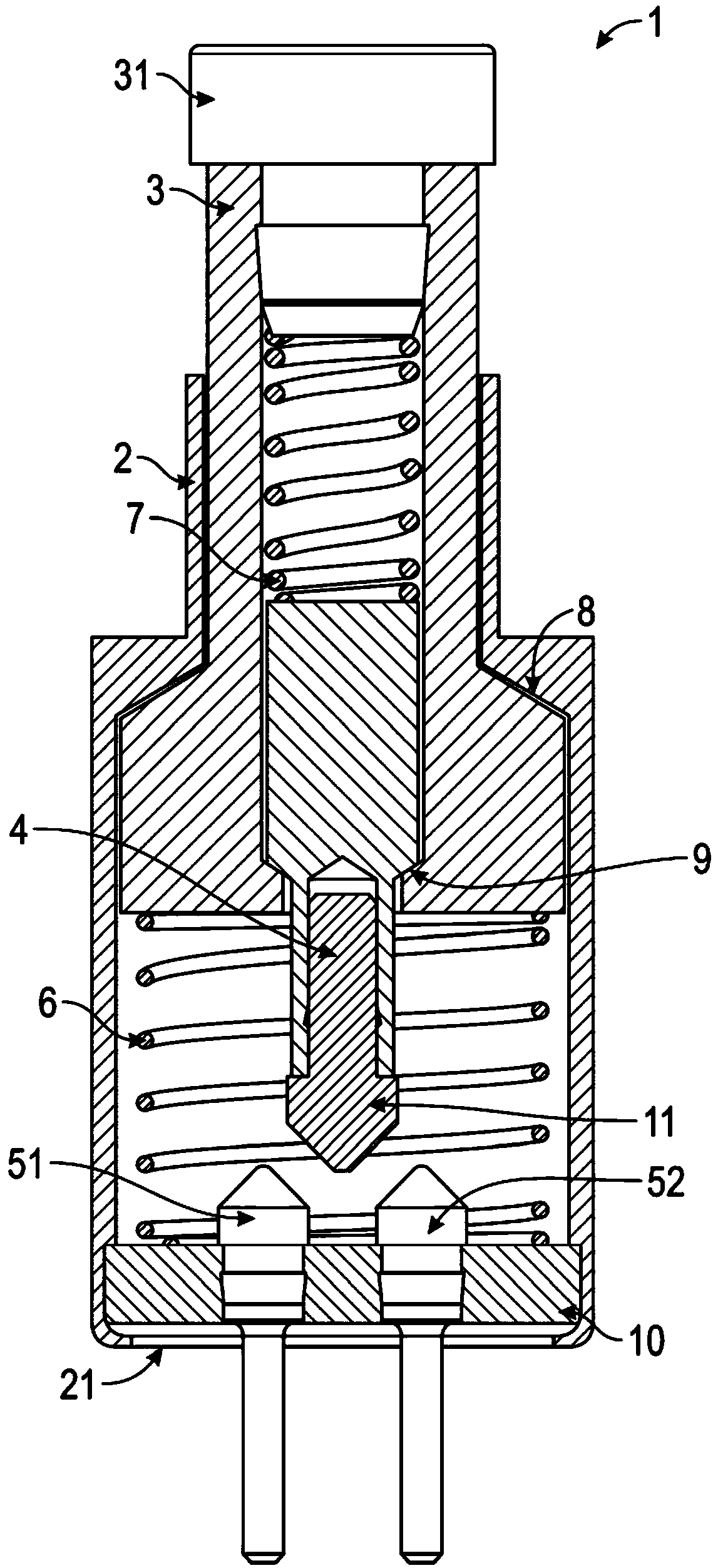
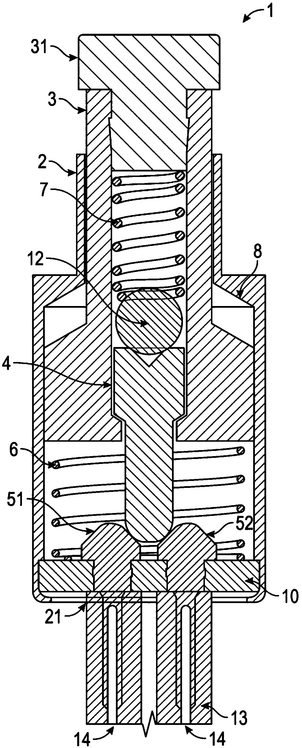
[0024] according to figure 1 The first microswitch 1 according to the invention comprises a cylindrical sleeve 2 with a narrowed and open neck from which a piston 3 protrudes. The piston 3 is also cylindrically shaped and is movably arranged in the sleeve 2 . There is only a small gap between the sleeve 2 and the piston 3 . The piston 3 can be pressed in the sleeve 2 in the direction of the sleeve bottom 21 , whereupon the piston 3 is separated from the sleeve 2 at a first inclined portion 8 open towards the sleeve bottom 21 which separates the sleeve 2 The neck is connected with a wide central base. When the piston 3 returns to the initial position due to the return spring 6 arranged at the sleeve bottom 21 or between the retaining plate 10 and the piston...


PUM


Abstract

The present invention relates to a microswitch that includes a cylindrical sleeve in which a piston is axially movably disposed. A contact pin is axially movably disposed within the piston. The contact pin interacts with two mating contacts that are fixed in the bottom of the sleeve spaced apart from one another. The movement of the contact pins is supported by two springs. A return spring is disposed between the bottom of the sleeve and the piston and moves the piston to an initial position when the microswitch is not actuated. A buffer spring is disposed between the contact pin and a pistonactuating cap and is responsible for gently placing the contact pin onto the mating contacts. In order to buffer the movement of the contact pin only shortly before being placed on the mating contacts, the buffer spring has a larger spring force than the return spring. The microswitch can be constructed with a stable metal sleeve and works despite the lack of insulation between the piston and thesleeve. The two mating contacts also result in a larger contact area and improved guiding of the contact pins.

Description

technical field [0001] The present invention relates to a microswitch and a test system for testing the presence of components such as cable harnesses. Background technique [0002] When manufacturing a cable harness, several components are fastened to the wire. If a component fails or cannot be installed in the correct position, subsequent repairs are complicated, since the installation of the cable harness in a technical installation, such as a motor vehicle, does not coincide with the production site, and repair equipment is not available. It is therefore important to test cable bundles during or after manufacture. [0003] A test system for testing a cable harness includes at least one component receptacle in which a microswitch is provided. The component receptacles are positioned on the build plate used to manufacture the cable harness in such a way as to allow the components to be tested for their presence and position to be pushed into the component receptacles. T...

Claims


Application Information

Patent Timeline
Patent Type & Authority Applications(China)
IPC IPC(8): H01H13/18H01H13/28H01H13/52
CPCH01H13/18H01H13/28H01H13/52H01H1/20H01H1/502H01H3/16H01H13/20
Inventor 曼努埃尔·卡格胡贝尔瑞纳·欧特
Owner LISA DRAXLMAIER GMBH
Why Eureka
Try Eureka