Combined automatic constant tension pneumatic twine tensioner

A rope tightener and constant tension technology, applied in the direction of motor vehicles, vehicles used for freight, transport objects, etc., can solve the problem of uneven force on both ends of the rope tightener, unable to tighten the rope in time, and difficult to fasten goods, etc. problem, to achieve the effect of compact structure, large bearing capacity and stable torque output

Pending Publication Date: 2017-12-12
帕瓦夫南通电气科技有限公司
View PDF8 Cites 0 Cited by
  • Summary
  • Abstract
  • Description
  • Claims
  • Application Information

AI Technical Summary

Problems solved by technology

[0002] After the car is loaded with goods, it is usually necessary to fasten the goods to the car with ropes. The fastening of the ropes often relies on manual pulling, and the disadvantage of manual tightening of the ropes is that the strength is small, and it is not easy to fasten the goods. During transportation, vibrations easily loosen the ropes. Loose ropes will cause the goods to shift, causing the vehicle to be heavily loaded, which will easily lead to transportation accidents and affect transportation safety. The force on both ends of the device is uneven, causing the rope to loosen, and the rope cannot be tightened in time, and it is easy to fall off

Method used


Image

  • Combined automatic constant tension pneumatic twine tensioner
  • Combined automatic constant tension pneumatic twine tensioner
  • Combined automatic constant tension pneumatic twine tensioner

Examples


Embodiment Construction

[0039] The technical solution of the present invention will be described in further detail below in conjunction with specific embodiments and accompanying drawings.

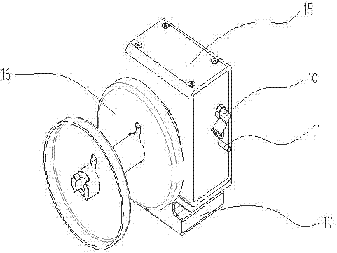
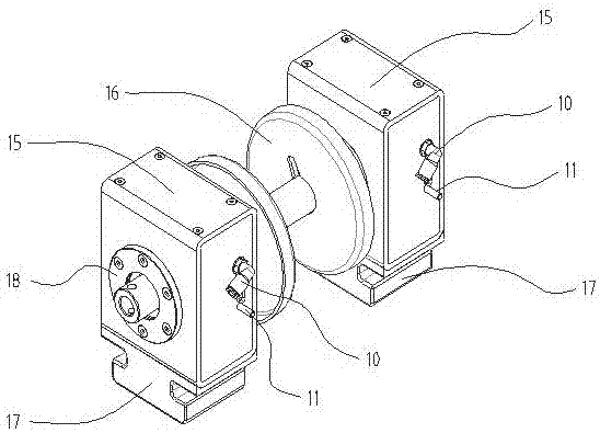
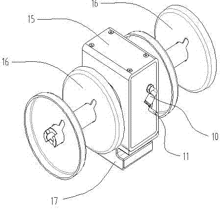
[0040] Such as figure 1 One embodiment shown is a combined automatic constant tension pneumatic rope tensioner, including a rope tensioner body and a reel assembly connected to the rope tensioner body, wherein one of the rope tensioner bodies is connected with a Reel assembly, this connection structure is suitable for occasions with general winding force requirements; such as figure 2 Another embodiment of the automatic constant tension pneumatic rope tensioner is shown, in which two rope tensioner bodies are connected with a reel assembly, which is suitable for occasions requiring higher winding force; image 3 In the automatic constant tension pneumatic rope tightener shown in the third embodiment, one rope tensioner body is connected with two reel assemblies, which is suitable for occasions requiring lower w...


PUM


Abstract

The invention discloses a combined automatic constant tension pneumatic twine tensioner. The combined automatic constant tension pneumatic twine tensioner comprises twine tensioner bodies and coiling block assemblies connected to the twine tensioner. One twine tensioner body is connected to one or more coiling block assemblies or one coiling block assembly is connected to the plurality of twine tensioner bodies. Each of the twine tensioner bodies comprises a power driving mechanism, a slide valve guiding mechanism and a stress housing and a clutch mechanism. The slide valve guiding mechanism is arranged on the side portion of the power driving mechanism, and the stress housing and the clutch mechanism are arranged on the outer side of the power driving mechanism and the slide valve guiding mechanism. By changing a conventional piston rod to a piston plate and arranging a transmission shaft and the piston plate in a cross manner, the transmission shaft and the piston plate do not interfere with each other; and two air cylinders which are mutually collaborated are adopted as a power driving source, and the steering structure is compact, small in size and large in bearing capacity.

Description

technical field [0001] The invention relates to a rope tensioner structure, in particular to a combined automatic constant tension pneumatic rope tensioner. Background technique [0002] After the car is loaded with goods, it is usually necessary to fasten the goods to the car with ropes. The fastening of the ropes often relies on manual pulling, and the disadvantage of manual tightening of the ropes is that the strength is small, and it is not easy to fasten the goods. During transportation, vibrations easily loosen the ropes. Loose ropes will cause the goods to shift, causing the vehicle to be heavily loaded, which will easily lead to transportation accidents and affect transportation safety. The uneven force on both ends of the device causes the rope to loosen, and the rope cannot be tightened in time, and it is easy to fall off. Contents of the invention [0003] Purpose of the invention: The purpose of the present invention is to solve the deficiencies in the prior a...

Claims


Application Information

Patent Timeline
Patent Type & Authority Applications(China)
IPC IPC(8): B60P7/08
CPCB60P7/0823B60P7/0846B60P7/0853
Inventor 缪煜张小宏吉铁山
Owner 帕瓦夫南通电气科技有限公司
Why Eureka
Try Eureka