Mask and mask manufacturing method

A manufacturing method and masking technology, which is applied in ion implantation plating, liquid chemical plating, coating, etc., can solve the problems of increasing the distortion of opening patterns, exceeding the tolerance of electronic components, and large deviations in tension and tension, etc., to achieve shrinking Tolerance range, avoidance of deformation or offset, effect of avoidance of errors

Pending Publication Date: 2022-03-01
DARWIN PRECISIONS CORP
View PDF7 Cites 0 Cited by
  • Summary
  • Abstract
  • Description
  • Claims
  • Application Information

AI Technical Summary

Problems solved by technology

However, tension stretching also causes deformation or offset of the opening pattern; and when the opening pattern is finer or the size is finer, the deviation caused by tension stretching is also larger, making the tolerance of electronic components exceed the appropriate range
In addition, etching and other processes also increase the chance of opening pattern distortion

Method used


Image

  • Mask and mask manufacturing method
  • Mask and mask manufacturing method
  • Mask and mask manufacturing method

Examples


Embodiment Construction

[0059] Below in conjunction with accompanying drawing, structural principle and working principle of the present invention are specifically described:

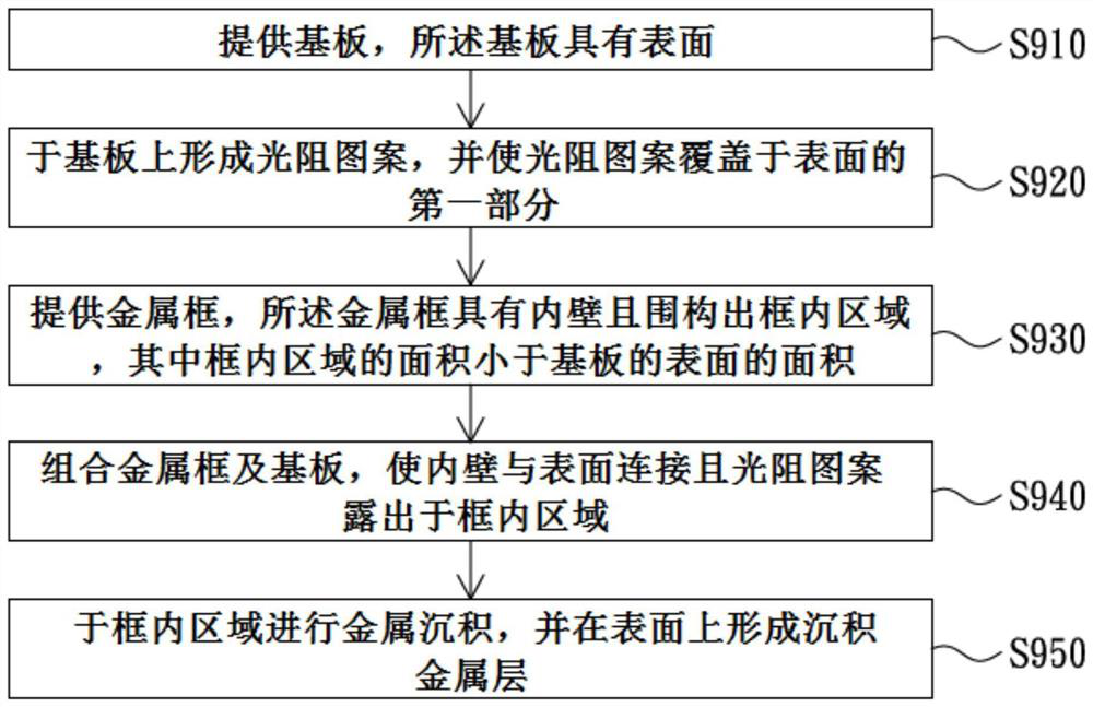
[0060] The invention provides a method for manufacturing a mask. Such as figure 1 As shown, in an embodiment of the present invention, the manufacturing method of the mask includes steps S910-S950. Further explanation is as follows.

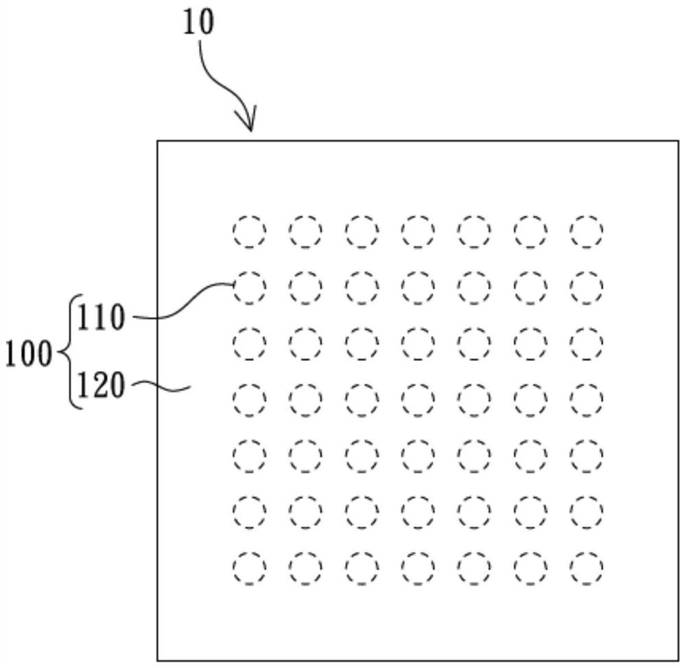
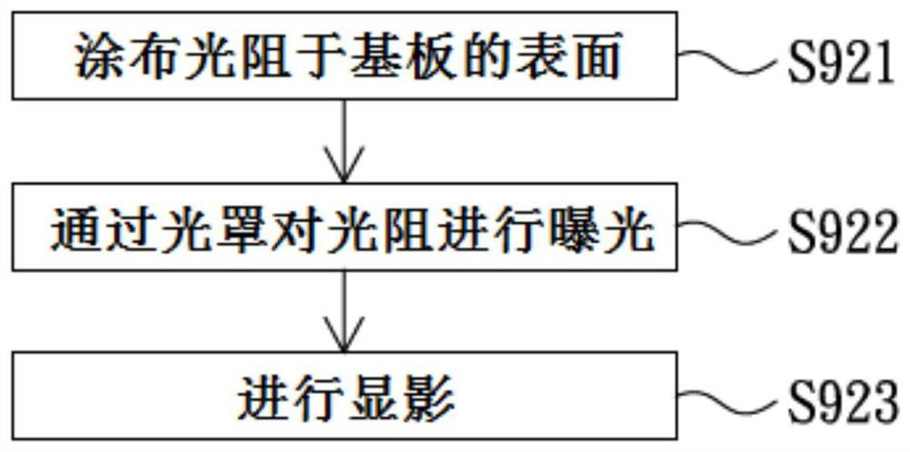
[0061] Step S910 is: providing a substrate, the substrate has a surface. Step S920 is: forming a photoresist pattern on the substrate, and making the photoresist pattern cover the first part of the surface. Please also refer to figure 2 In this embodiment, the surface 100 of the substrate 10 may include the first portion 110 , and may further include the second portion 120 . The first part 110 and the second part 120 can be pre-planned virtual areas corresponding to electronic components, and for example, circuit patterns, pixel structures, etc. are also objects that can be used to plan the...


PUM

PropertyMeasurementUnit
thicknessaaaaaaaaaa
pore sizeaaaaaaaaaa

Abstract

A method for manufacturing a mask includes the steps of: providing a substrate having a surface; forming a photoresist pattern on the substrate, and enabling the photoresist pattern to cover the first part of the surface; a metal frame is provided, the metal frame is provided with an inner wall and defines an in-frame area, and the area of the in-frame area is smaller than that of the surface of the substrate; combining the metal frame and the substrate so that the inner wall is connected with the surface and the photoresist pattern is exposed out of the in-frame region; and performing metal deposition in the in-frame region, and forming a deposited metal layer on the surface. The invention also provides a mask.

Description

technical field [0001] The invention relates to a manufacturing method of a mask, in particular to an integrated manufacturing method of a metal mask. Background technique [0002] Advances in mobile technology and trends in the miniaturization and weight reduction of mobile devices have brought new challenges to the forming and manufacturing of electronic components. Taking passive components as an example, their manufacture relies on processes such as sputtering, evaporation, and printing. The masks used in these processes are composed of a frame and a metal film fixed on the frame. Generally speaking, the metal film is provided through photolithography, etching, and has an opening pattern. Because the metal film is flexible, the metal film needs to be stretched under tension before being bonded to the frame during fixing. However, the tension stretching also causes deformation or offset of the hole pattern; and when the hole pattern is finer or the size is finer, the d...

Claims


Application Information

Patent Timeline
Patent Type & Authority Applications(China)
IPC IPC(8): C23C14/04C23C18/16C25D1/08C25D1/10
CPCC23C14/042C23C18/1605C23C18/1657C25D1/08C25D1/10C23C14/24C23C14/04
Inventor 林仁顺
Owner DARWIN PRECISIONS CORP
Why Eureka
Try Eureka