Feed feeding vehicle for livestock breeding

A feed and feeding port technology, applied in the field of aquaculture, can solve the problems of low feeding amount, low efficiency, easy agglomeration of feed, etc., and achieve the effects of convenient operation, prevention of feed clogging and simple structure

CN109380133AInactive Publication Date: 2019-02-26广西领测科技有限公司
0 Cites 0 Cited by

Patent Information

Authority / Receiving Office
CN · China
Current Assignee / Owner
Publication Date
2019-02-26
Estimated Expiration
Not applicable · inactive patent

Smart Images

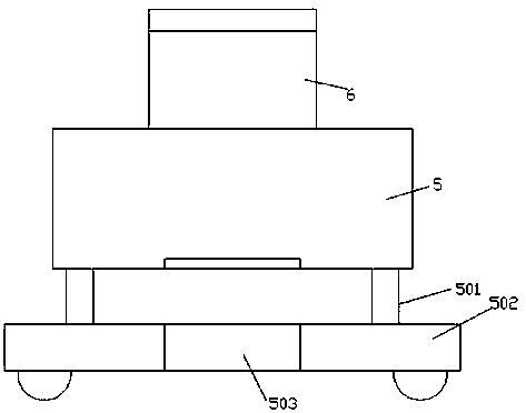
  • Figure 1
    Figure 1
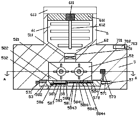
  • Figure 2
    Figure 2
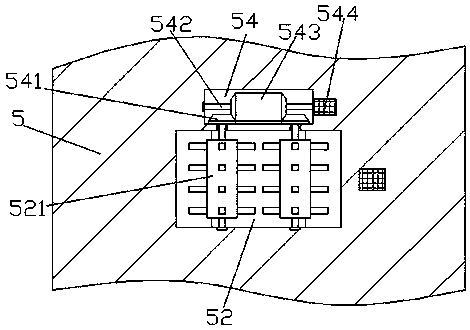
  • Figure 3
    Figure 3
Patent Text Reader

Abstract

The invention discloses a feed feeding vehicle for livestock breeding, which comprises a feed feeding machine body and a mixing box arranged at the top of the feed feeding machine body. The mixing boxis internally provided with a mixing cavity. The bottom of the mixing cavity is provided with a conical cavity which extends downwards, and the extension of the bottom of the conical cavity extends into the feed feeding machine body. The bottom end of the conical cavity is provided with a discharge port in a penetrating way, and the bottom surface of the feed feeding machine body is provided witha discharge groove in which the top end and the bottom end of the discharge port are arranged in a penetrating way. The inner walls of the left side and the right side of the discharge groove are correspondingly provided with sliding grooves. The top wall of each sliding groove is provided with a guide groove. A feed feeding device is arranged between the left and right sliding grooves, and is connected to the discharge groove and the sliding groove in a sliding and matching way. The top part of the left and right bottom of the feed feeing device in the left and right sliding grooves are respectively provided with guide blocks extending into the guide grooves at the left side and the right side and are connected with each other in a sliding manner. The feed feeding vehicle is simple in structure and convenient to operate. The feed feeding vehicle can also control different feed feeding amounts automatically, so that the feed feeding efficiency is improved.
Need to check novelty before this filing date? Find Prior Art

Description

Technical field

[0001] The invention relates to the technical field of breeding, in particular to a feed feeding vehicle for livestock breeding. Background technique

[0002] At present, the prospects of my country's animal husbandry industry are optimistic, but the breeding technology is still relatively traditional. Most of the feed is manually mixed and mixed and fed. This method is time-consuming, laborious, inefficient, and the feed tends to agglomerate, and the feeding amount cannot be accurately controlled. , Resulting in too little or too much feeding, which is not conducive to the growth of livestock. Summary of the invention

[0003] The technical problem to be solved by the present invention is to provide a feed feeding vehicle for animal husbandry, which can solve the above-mentioned problems in the current technology.

[0004] The present invention is achieved through the following technical solutions: a feed feeding vehicle for animal husbandry of the present invention...

Examples

Embodiment Construction

[0025] Such as Figure 1-Figure 5 As shown, a feed-feeding vehicle for animal husbandry of the present invention includes a feed-feeding body 5 and a mixing box 6 installed on the top of the feed-feeding body 5, and a mixing chamber 61 is provided in the mixing box 6. The bottom of the mixing chamber 61 is provided with a downwardly extending cone-shaped cavity 62, the bottom extension of the cone-shaped cavity 62 extends into the feed feeding machine body 5, and the bottom and tail of the cone-shaped cavity 62 is penetrated with Discharge outlet 51, the bottom surface of the feed feeding body 5 is provided with a discharge groove 52 with a top and a bottom end of the discharge port 51 penetratingly arranged. The inner walls of the left and right sides of the discharge groove 52 are correspondingly provided with sliding grooves 53. The inner top wall of each of the sliding grooves 53 is provided with a guide groove 532, and between the sliding grooves 53 on the left and right s...