
Car engine compartment lighting strut

An engine and automobile technology, applied in the field of automobile engine compartment lighting struts, can solve problems such as easy detection errors, misjudgment, inconvenient bulb replacement, etc., and achieve the effect of easy detection and maintenance, novel and ingenious ideas

Inactive Publication Date: 2020-05-12
杭州技师学院
View PDF14 Cites 0 Cited by
  • Summary
  • Abstract
  • Description
  • Claims
  • Application Information

AI Technical Summary

Problems solved by technology

[0002] The engine compartment of the car is the place where problems are most likely to occur, and the engine compartment needs to be inspected and maintained frequently. When performing the above operations, you need to open the engine compartment cover first, and prop it up with the struts configured in the compartment to ensure After stabilization, the components in the cabin are inspected. When performing related inspections outdoors, especially in the dark or when the external light is weak, it is usually necessary for the inspector to hold the power supply to illuminate or set up other lighting equipment to allow the inspector to operate. Inconvenient, waste of time, easy to detect errors, lead to misjudgment, and can not find the source of the problem. In the prior art, there is a way of using struts for lighting, but its structural stability is poor, and it does not take into account the high ambient temperature of the cabin, Problems such as inconvenient replacement of light bulbs

Method used


Image

  • Car engine compartment lighting strut
  • Car engine compartment lighting strut
  • Car engine compartment lighting strut

Examples


Embodiment Construction

[0030] The present invention will be described in further detail below in conjunction with the accompanying drawings and specific embodiments.

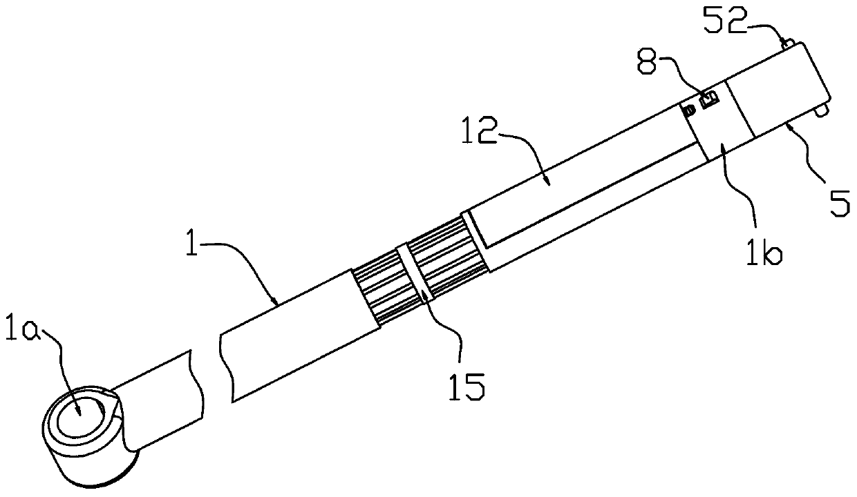
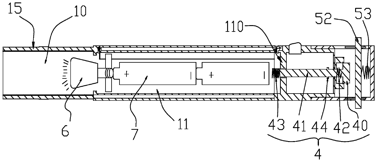
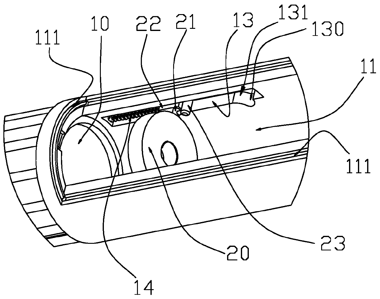
[0031] refer to Figure 1 to Figure 7 The shown automotive engine compartment lighting strut mainly includes a cylindrical rod-shaped strut body 1, a ball head 1a is installed on one end of the strut body 1, and the other end is a pole top 1b (hereinafter referred to as the pole top 1b end). The upper part, the other end is the lower part), the pole body 1 has a hollow section at the end close to the pole top 1b, the section close to the ball head 1a in the hollow section is divided into the lighting compartment 10, and the section close to the pole top 1b is divided into the power supply compartment 11, The two chambers are connected to each other, wherein the side wall of the lighting chamber 10 is made of transparent vacuum glass, and a hollow explosion-proof cover 15 is provided on its outer wall cover. The explosion-proof cover 1...


PUM


Abstract

The invention discloses an automobile engine cabin lighting supporting rod. The automobile engine cabin lighting supporting rod comprises a hollow supporting rod body. The hollow supporting rod body is internally provided with a lighting bin and a power supply bin. The power supply bin is provided with an installation opening, a cover plate matched with the installation opening is arranged, and the cover plate is in sliding fit with the supporting rod body. The power supply bin is internally and movably provided with a lamp holder and a battery. The lamp holder is provided with a bulb. The bulb is pushed into the lighting bin through a battery shell. A holder body of the lamp holder can be turned by 90 degrees to be right opposite to the installation opening. The rod top is provided with acontact switch and a supporting head. The supporting head is internally provided with a supporting plate which is movably arranged. The supporting plate can move towards a button of the contact switch and presses the button, and therefore an electric shock guide rod of the contact switch makes contact with a negative electrode of the battery, and closing of a circuit between the bulb and the battery is achieved. The opening and closing states of the button of the contact switch are controlled through the supporting plate so that the contact switch is controlled, lighting equipment stops working, and the changing problem of the bulb is sufficiently considered; and installing and changing of the bulb are achieved by automatically exiting the overturning angle, and the conception is novel and ingenious.

Description

technical field [0001] The invention belongs to the structural field of automobile parts, and in particular relates to a lighting strut for an automobile engine compartment. Background technique [0002] The engine compartment of the car is the place where problems are most likely to occur, and the engine compartment needs to be inspected and maintained frequently. When performing the above operations, you need to open the engine compartment cover first, and prop it up with the struts configured in the compartment to ensure After stabilization, the components in the cabin are inspected. When performing related inspections outdoors, especially in the dark or when the external light is weak, it is usually necessary for the inspector to hold the power supply to illuminate or set up other lighting equipment to allow the inspector to operate. Inconvenient, waste of time, easy to detect errors, lead to misjudgment, and can not find the source of the problem. In the prior art, ther...

Claims


Application Information

Patent Timeline
Patent Type & Authority Patents(China)
IPC IPC(8): E05C17/12B60Q3/30F21V33/00
CPCB60Q3/30E05C17/12F21V33/00
Inventor 夏晓张登裕王殿虎
Owner 杭州技师学院
Learn More