
Daylight hand-lamp for checking painted surfaces, in particular in the field of paint repair work on motor vehicles
A technology for flashlights and motor vehicles, applied to optical elements for changing the spectral characteristics of emitted light, electric lighting devices with built-in batteries, planar light sources, etc., can solve problems such as difficult to detect, and achieve good performance effects
- Summary
- Abstract
- Description
- Claims
- Application Information
AI Technical Summary
Problems solved by technology
Method used
Image

Examples
Embodiment Construction
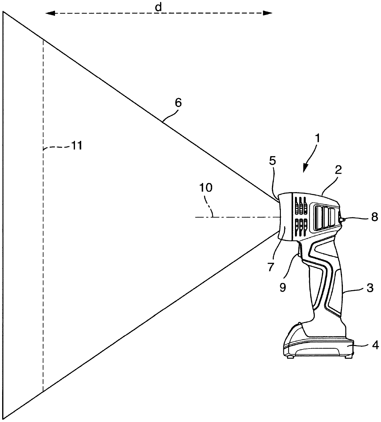
[0055] figure 1 Shown is a daylight torch 1 for inspecting painted surfaces, in particular in the context of motor vehicle restoration work. The flashlight 1 has a head part 2 , a handle part 3 and, below the end of the handle part 3 , a releasably fastened accumulator 4 , in particular a lithium-ion accumulator. On its front side, the head part 2 has a light outlet 5 through which a light beam 6 can exit. A light 7 is arranged in the head part 2 in order to generate the light beam 6 . exist figure 1 In the figure, the head part 2 is shown partially cut away in the region of the light outlet 5 in order to show at least a part of the illuminant 7 .
[0056] Arranged on the rear side of the head part 2 is an operating element 8 by means of which the light intensity of the generated light beam 6 can be adjusted, for example, within a range of 50% to 100% of the maximum light intensity. On the side facing away from the operating element 8 and below the head 2 there is arranged...
PUM
 Abstract
Description
Claims
Application Information