
Rotating shaft module of folding device

A folding and rotating shaft technology, applied in the direction of pivot, shaft and bearing, pivot connection, etc., can solve the problems of wrinkling or peeling, slow shrinkage, connection relationship and complex structure of the middle bending part of the flexible display

Active Publication Date: 2019-04-19
JARLLYTEC CO LTD
View PDF13 Cites 17 Cited by
  • Summary
  • Abstract
  • Description
  • Claims
  • Application Information

AI Technical Summary

Problems solved by technology

[0004] However, the connection relationship and structure of the parts of the mechanism that can compensate the folding path used in the above-mentioned patents are quite complicated, and most of them use a direct pivot structure, which is not ideal in terms of transmission stability, and its supporting structure In the process of generating displacement to reduce the distance to accommodate the bending part of the flexible display, because the relative movement to reduce the speed is the same or too slow, it is easy to be caused by the uneven force of the folding action or the displacement speed of the supporting structure. Not fast enough to quickly create space to accommodate the bend of the flexible display, causing pulling or jostling of the flexible display, wrinkling or peeling of the middle bend of the flexible display

Method used


Image

  • Rotating shaft module of folding device
  • Rotating shaft module of folding device
  • Rotating shaft module of folding device

Examples


Embodiment Construction

[0068] The technical solutions in the embodiments of the present invention are clearly and completely described below in conjunction with the drawings in the embodiments of the present invention. In the following description, a lot of specific details are set forth in order to fully understand the present invention, but the present invention can also be implemented in other ways different from those described here, and those skilled in the art can do it without departing from the meaning of the present invention. By analogy, the present invention is therefore not limited to the specific examples disclosed below.

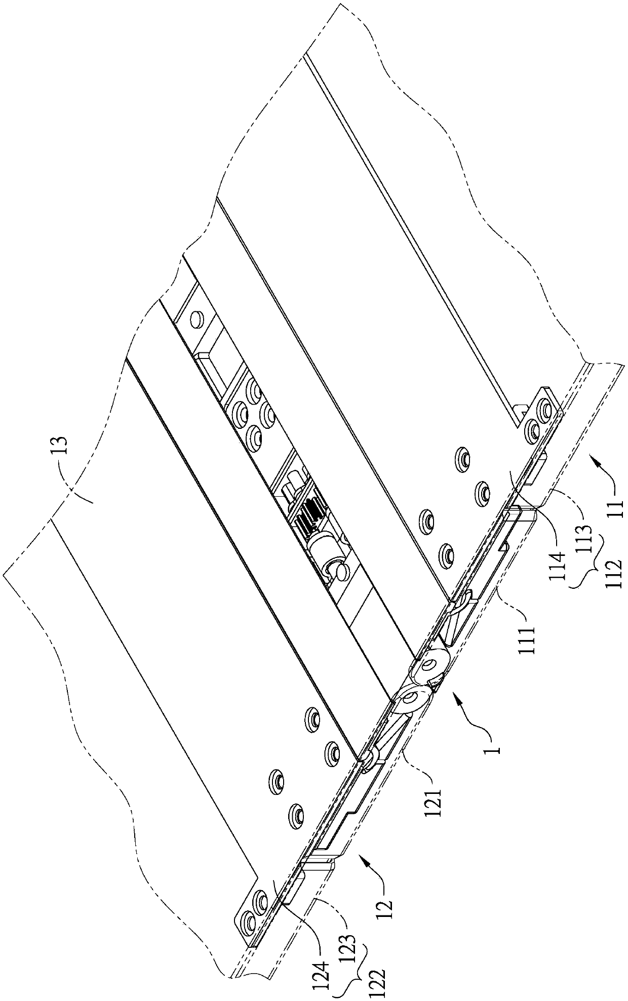
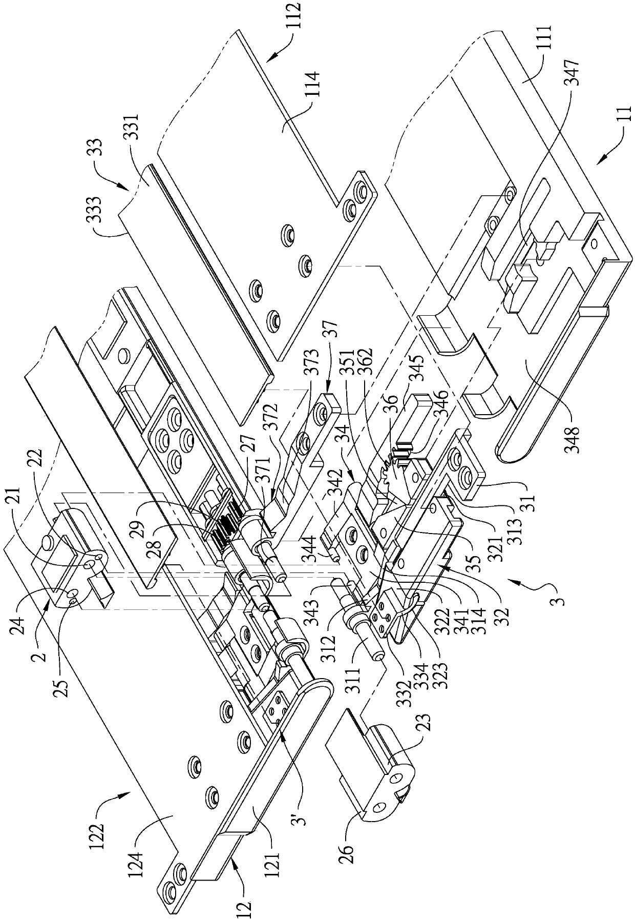
[0069] see figure 1 As shown, one end surface of the hinge module 1 of the folding device of the present invention contacts the two halves of a flexible display 13 at the same time, and the other end surface of the hinge module 1 is respectively connected to a first housing 11 and a second housing 12, for linking the first shell 11 and the second shell 12, so that ...


PUM


Abstract

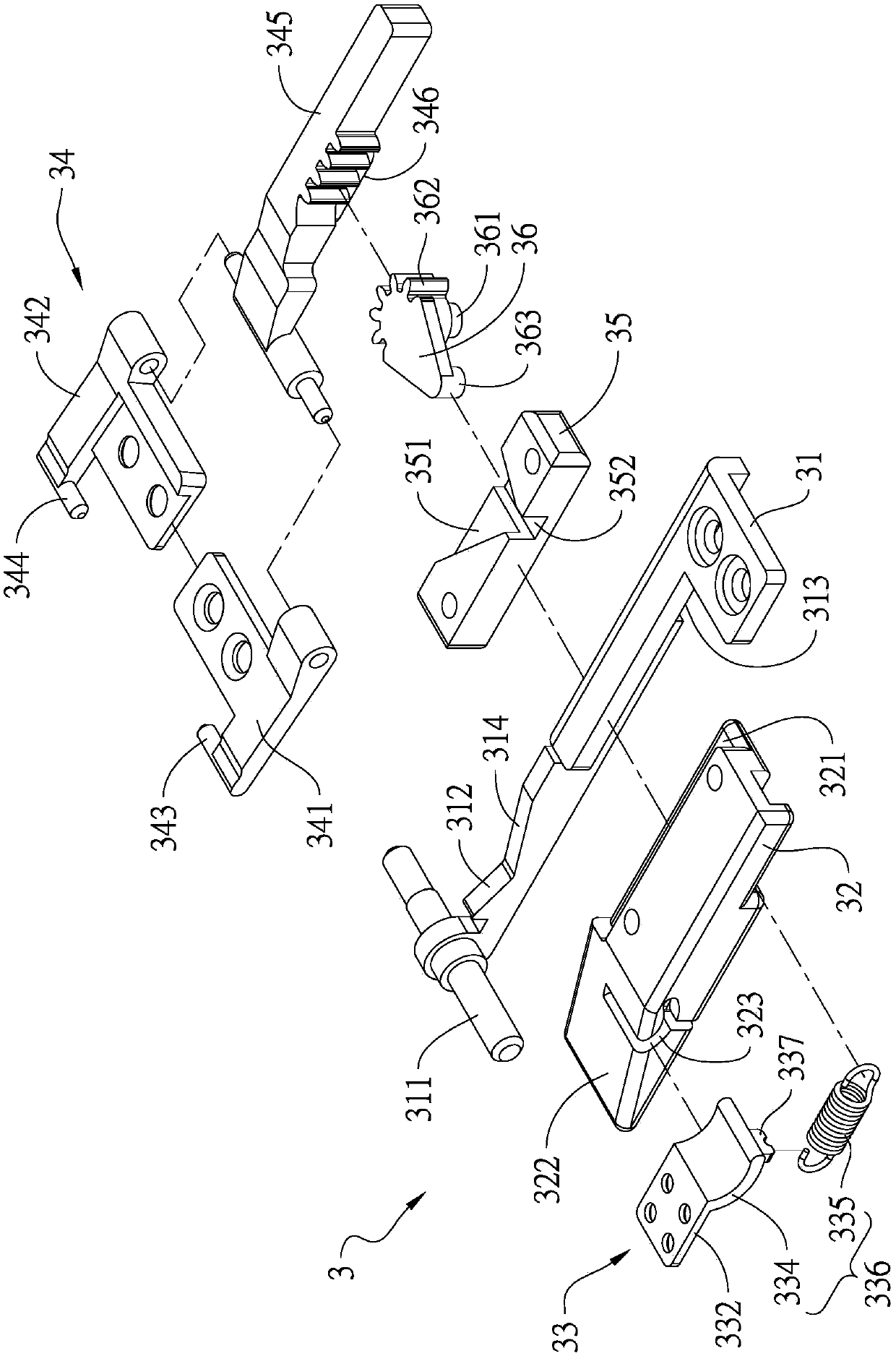
The invention provides a rotating shaft module of a folding device. On end surface of the rotating module of the folding device is in contact with a flexible display; the other end surface of the rotating module of the folding device is respectively connected with a first shell and a second shell; the rotating module comprises a base and a first sliding mechanism; the first sliding mechanism comprises a first connection rod, a first sliding block, a support plate body, a linkage plate, a linkage part and an intermediate driving part; the first connection rod and the linkage plate are respectively pivotally connected to a first pivoting part and a second pivoting part of the base; a limiting part at one end of the support plate body is limited on a first stop part of the base; a second connection part at the other end of the support plate body is connected with a first connection part of the first sliding block in a relatively arc-shaped swinging manner; a first rack of the linkage plate is toothed with a gear part of the intermediate driving part; one end of the intermediate driving part is slidably located on the linkage part, so that the support plate body is offset so as to receive a bending part of the flexible display.

Description

technical field [0001] The invention relates to a hinge, in particular to a hinge module of a foldable electronic device. Background technique [0002] Traditional folding electronic devices, such as the foldable display patent with the notification number CN105788452 A, discloses a folding structure of a rotating shaft, which mainly uses the first main body and the third main body of the hinge to connect with the first support respectively. The member and the second supporting member are connected to each other, and the first supporting member and the second supporting member are combined with a flexible display module, so that after the first main body and the third main body rotate relative to the second main body, the first supporting member and the second supporting member The flexible display modules on the second supporting member are folded together. Since it is necessary to install a structure on the second body that allows the first and third bodies to rotate, it ...

Claims


Application Information

Patent Timeline
IPC IPC(8): F16C11/04
CPCF16C11/045
Inventor 许有村
Owner JARLLYTEC CO LTD
Learn More