Hinge module for folding units

A folding and rotating shaft technology, applied in the direction of identification device, pivot connection, instrument, etc., can solve the problem of affecting the overall thickness and so on

Active Publication Date: 2022-02-01
JARLLYTEC CO LTD
View PDF9 Cites 0 Cited by
  • Summary
  • Abstract
  • Description
  • Claims
  • Application Information

AI Technical Summary

Problems solved by technology

[0002] The applicant once applied for an invention patent application titled "Rotating Shaft Module of a Foldable Device" (application number TW107113396 / CN201810371007.2, hereinafter referred to as previous case 1), one of the embodiments includes a first support member, a pair of The open shaft, the second supporting member, the multi-axis rotating shaft and the third supporting member are for use with a flexible display device, so that after the whole is folded into an S-shape, the first split shaft connected The support member and the second support member can be closed, and will form an accommodating space inside the split-type rotating shaft to accommodate the curved area of ​​the flexible display, but in terms of the multi-axis rotating shaft, limited It is limited to keep a sufficient distance between the four shafts for the installation of other components (such as linkages, friction plates, linkage plates and stoppers, etc.), so after the overall folding, the multi-axis shaft There will be a gap between the connected second support and the third support. When the flexible display needs to be arranged on the same side of the three supports, the split shaft and the multi-axis shaft, the aforementioned spacing will affect the overall thickness

Method used


Image

  • Hinge module for folding units
  • Hinge module for folding units
  • Hinge module for folding units

Examples


Embodiment Construction

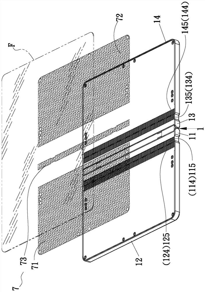
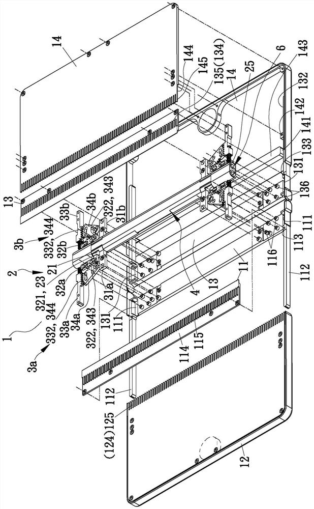
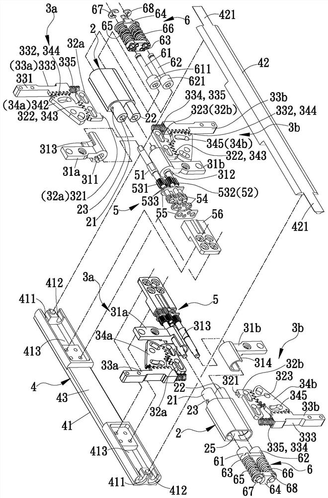
[0078] see Figure 1 to Figure 8As shown, it is the first embodiment of the hinge module 1 of the present invention. The opposite ends of the hinge module 1 are respectively connected with a shell base, and a flexible display F is installed on the same side of the hinge module 1 and each shell base. The flexible display F can be turned into a folded or unfolded shape along with the two shell seats; the hinge module 1 includes a base 2, a first sliding mechanism 3a, and a second sliding mechanism 3b. A sliding mechanism 3a is connected to one housing, and the second sliding mechanism 3b is connected to another housing. The first sliding mechanism 3a and the second sliding mechanism 3b form a corresponding structure, and are symmetrically arranged on the base. At the opposite ends of the seat 2, an extension base 4 and at least one hinge device 5 are further provided between the two shell seats, and the at least one hinge device 5 is arranged at least one installation part in th...


PUM


Abstract

The invention relates to a hinge module of a folding device, which is connected with two housing bases, so that a matching flexible display can be turned into a folded or unfolded shape with relative flipping, and each housing base includes two housings that can slide relatively body, the rotating shaft module includes a base and two sliding mechanisms, and one end of the two connecting pieces of each sliding mechanism is respectively pivotally connected to the two shafts of the base to guide the two axial directions of each sliding mechanism ( Steering) the displacement of the driving part, and then connect a housing through the opposite ends of the respective connecting parts and each radial linkage part, set the guide structure on the side and end side between the two housings, and pass through the steering transmission parts The transmission effect between each axial (steering) drive member and each radial linkage member, as well as the mutual guidance between each housing, allow each housing base to be able to expand and contract stably, and use the displacement path to compensate for the movement of the flexible display. The length changes after bending, so that the bending part has a small curvature.

Description

technical field [0001] The invention relates to a hinge, especially a hinge module of a foldable electronic device. Background technique [0002] The applicant once applied for an invention patent application titled "Rotating Shaft Module of a Foldable Device" (application number TW107113396 / CN201810371007.2, hereinafter referred to as previous case 1), one of the embodiments includes a first support member, a pair of The open shaft, the second supporting member, the multi-axis rotating shaft and the third supporting member are for use with a flexible display device, so that after the whole is folded into an S-shape, the first split shaft connected The support member and the second support member can be closed, and will form an accommodating space inside the split-type rotating shaft to accommodate the curved area of ​​the flexible display, but in terms of the multi-axis rotating shaft, limited It is limited to keep a sufficient distance between the four shafts for the inst...

Claims


Application Information

Patent Timeline
Patent Type & Authority Patents(China)
IPC IPC(8): F16C11/04G09F9/30
CPCF16C11/04G09F9/301
Inventor 许有村
Owner JARLLYTEC CO LTD
Why Eureka
Try Eureka