Crystal lamp structure

A technology of crystal lamps and crystal strings, which can be used in lighting devices, fixed lighting devices, electric light sources, etc., and can solve problems such as the poor effect of colored light emitted from chandeliers

Inactive Publication Date: 2019-05-17
UNILED LIGHTING TW
View PDF8 Cites 2 Cited by
  • Summary
  • Abstract
  • Description
  • Claims
  • Application Information

AI Technical Summary

Problems solved by technology

therefore, Figure 1A The effect of the overall color light output of the chandelier is not good

Method used


Image

  • Crystal lamp structure
  • Crystal lamp structure
  • Crystal lamp structure

Examples


Embodiment Construction

[0030] The present invention will be further elaborated below in conjunction with the accompanying drawings and specific embodiments. These examples should be understood as only for illustrating the present invention but not for limiting the protection scope of the present invention. After reading the contents of the present invention, those skilled in the art can make various changes or modifications to the present invention, and these equivalent changes and modifications also fall within the scope defined by the claims of the present invention.

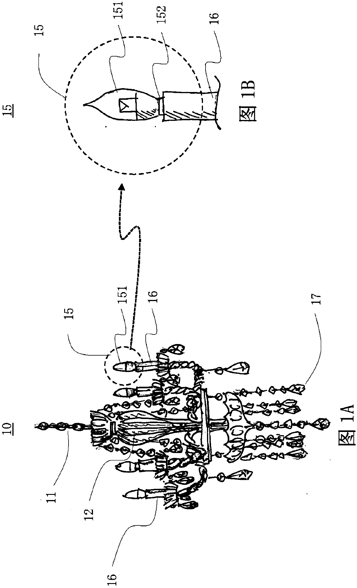
[0031] Figure 2A-2B A chandelier using the crystal light structure of the present invention is shown.

[0032] Figure 2A A chandelier using the crystal lamp structure of the present invention as a light source is shown. Figure 2A A chandelier 20 is shown, including a frame 12 , which is suspended from above by a rope 11 . The frame 12 has a lamp socket 16 for placing the light emitting unit 200 . The crystal string 17 is arr...


PUM


Abstract

The invention relates to a crystal lamp structure suitable for a ceiling lamp light source. In the preferred embodiment, a crystal bulb is provided with a light-emitting unit, a lamp holder, an innerring frame, an outer ring frame, outer ring crystal strings and inner ring crystal strings. The light-emitting unit is arranged above the lamp holder, and an annular frame is arranged on the upper surface of the light-emitting unit light-transmitting shell and provided with the outer annular frame and the inner annular frame. The outer ring crystal strings are hung on the outer ring frame, the inner ring crystal strings are hung on the inner ring frame, the inner ring crystal strings surround the periphery of the light-emitting unit, and the outer ring crystal strings surround the periphery ofthe inner ring crystal strings. Light emitted by the light emitting unit is split by the inner ring crystal strings for the first time to generate first color light, the first color light is split bythe outer ring crystal strings for the second time to generate second color light. The crystal lamp structure is used for color light visual decoration.

Description

technical field [0001] The invention relates to a crystal lamp structure, in particular to a crystal lamp structure suitable for a chandelier. Background technique [0002] Traditional crystal lamps have crystal hanging strings, and the crystals in them can reflect or refract light to produce colored light effects and provide decorative functions. [0003] Figure 1A A conventional chandelier 10 is shown, comprising a frame 12 suspended from above by means of slings 11 . The frame 12 has a lamp socket 16 for placing the light emitting unit 15 . The crystal string 17 is arranged under the frame 12 and hangs downward. Figure 1A The disadvantage of the shown chandelier 10 is that there are no water chips around the light emitting unit 15 at the upper end of the chandelier to provide the function of emitting colored light. [0004] Figure 1B show Figure 1A The light-emitting unit 15 used; the light-emitting unit 15 includes a bulb 151 , which is placed in the base 16 with ...

Claims


Application Information

Patent Timeline
IPC IPC(8): F21S8/06F21V17/10F21V7/00F21V19/00
Inventor 林明德林明耀
Owner UNILED LIGHTING TW
Why Eureka
Try Eureka