Arbitrary boundary optical element uniline non-intersected random machining path planning method

A technology for optical components and processing paths, which is applied in the field of random path planning for small tool processing, and can solve problems such as difficulty in adapting to arbitrary boundary optical components, intermediate frequency errors, and crossing paths.

Active Publication Date: 2019-05-17
SHANGHAI INST OF OPTICS & FINE MECHANICS CHINESE ACAD OF SCI
View PDF8 Cites 5 Cited by
  • Summary
  • Abstract
  • Description
  • Claims
  • Application Information

AI Technical Summary

Problems solved by technology

[0004] The purpose of the present invention is to solve the technical problem that the existing grating path, spiral path and pseudo-random path are difficult to use a single path to walk through the full aperture of any boundary optical element, or can walk through the full aperture of any boundary optical element but the paths intersect
Improving the traditional grating, spiral and other regular processing paths will bring obvious intermediate frequency errors due to path residuals, overcoming the problem that traditional regular processing paths or pseudo-random paths are difficult to adapt to arbitrary boundary optical elements

Method used


Image

  • Arbitrary boundary optical element uniline non-intersected random machining path planning method
  • Arbitrary boundary optical element uniline non-intersected random machining path planning method
  • Arbitrary boundary optical element uniline non-intersected random machining path planning method

Examples


Embodiment Construction

[0040] The present invention will be further described below in conjunction with the embodiments and accompanying drawings, but the protection scope of the present invention should not be limited thereto.

[0041] A method for generating a computer-controlled small tool processing path for an arbitrary boundary optical element, comprising the following steps:

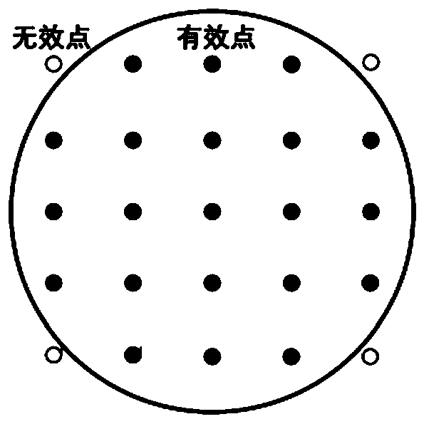
[0042] Step 1: Create three empty sets: a set of path points, a set of non-path points and a set of adjacent points. The elements in the three sets are the coordinate pairs corresponding to the points: (abscissa, ordinate). The set of waypoints is ordered, the set of non-waypoints and the set of adjacent points are unordered. figure 1Shown is a schematic diagram of the mesh division. The caliber of the component to be processed is divided into grids, and the grid spacing is equal to the grid spacing when calculating the dwell time. Select a full-caliber rectangular area that can cover the continuation distance as the ...


PUM


Abstract

The invention provides an arbitrary boundary optical element uniline non-intersected random machining path generation method. The method comprises the steps of defining path point, adjacent point andnon-path point sets, wherein each element in the sets is coordinates of each point; carrying out first random sampling on the adjacent point set, adding a point to the path point set if at least one sampling result satisfies a condition of adding the point (a feasible point) to the path point set, and extracting the point from the adjacent point set and the non-path point set; carrying out secondary random sampling on the adjacent point set if no sampling result satisfies the condition of adding the point to the path point set, modifying the point if at least one sampling result satisfies thecondition of a modificable point, returning path point elements between two endpoints of a modification side to the adjacent point set and the non-path point set, and adding the modificable point to the path point set; and carrying out two times of random sampling repeatedly, until the adjacent point set is empty, thereby obtaining a uniline non-intersected eight-direction random path applicable to arbitrary boundary.

Description

technical field [0001] The invention belongs to the field of advanced optical manufacturing and detection, and mainly relates to a small tool processing random path planning method used in the computer-controlled small tool surface forming process. Background technique [0002] In optical processing, the surface shape error data of the optical element surface after previous processing can usually be obtained according to various measurement methods. By planning a certain number and arrangement of dwell points on the component surface, the dwell time distribution corresponding to the dwell points can be calculated. Usually the dwell points are arranged in a uniform grid to ensure the reliability of the conversion between dwell time and dwell speed. The processing path is a connection method to connect these dwell points in series. Reasonable planning of the processing path can improve the processing quality and processing efficiency. The current mainstream processing paths ...

Claims


Application Information

Patent Timeline
Patent Type & Authority Applications(China)
IPC IPC(8): G05B19/19
Inventor 李徐钰魏朝阳徐文东邵建达
Owner SHANGHAI INST OF OPTICS & FINE MECHANICS CHINESE ACAD OF SCI
Why Eureka
Try Eureka