Eureka AIR delivers breakthrough ideas for toughest innovation challenges, trusted by R&D personnel around the world.

Backlight module and display device

A technology of backlight module and display device, which is applied in the directions of identification device, optics, nonlinear optics, etc., and can solve problems such as inability to use

Inactive Publication Date: 2019-06-18
WUHAN CHINA STAR OPTOELECTRONICS TECH CO LTD
View PDF0 Cites 27 Cited by
  • Summary
  • Abstract
  • Description
  • Claims
  • Application Information

AI Technical Summary

Problems solved by technology

However, in the application of terminal equipment, transparent display devices cannot use traditional backlight and external light as the light source of the display mode.
[0003] Therefore, it is necessary to propose a new backlight module and transparent display device to increase the screen-to-body ratio of the display device and solve the problem that the transparent display device in the prior art cannot use traditional backlight and external light as the light source of the display mode.

Method used


Image

  • Backlight module and display device
  • Backlight module and display device
  • Backlight module and display device

Examples


Embodiment Construction

[0025] The following description of various embodiments is made with reference to the accompanying drawings to illustrate specific embodiments in which the invention may be practiced. The directional terms mentioned in the present invention, such as up, down, front, back, left, right, inside, outside, side, etc., are only directions referring to the drawings. The component names mentioned in the present invention, such as first, second, etc., are only used to distinguish different components, which can be better expressed. In the figures, structurally similar elements are denoted by the same reference numerals.

[0026] Embodiments of the present invention will be described in detail herein with reference to the accompanying drawings. This invention may be embodied in many different forms and should not be construed as only the specific embodiments set forth herein. These embodiments are provided to explain the practical application of the invention, so that others skilled i...


PUM


Abstract

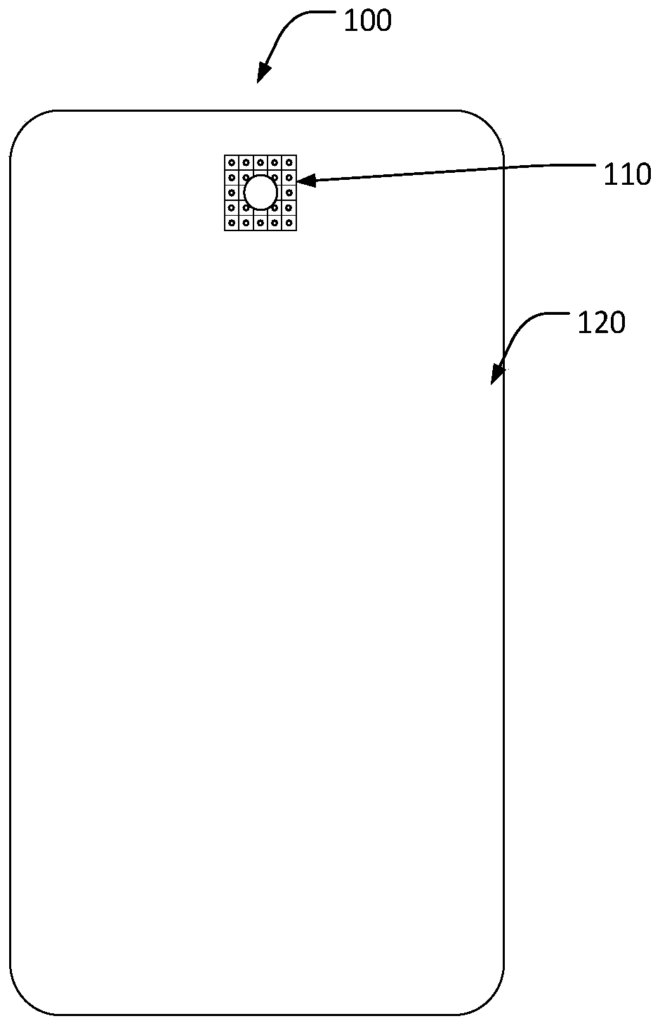
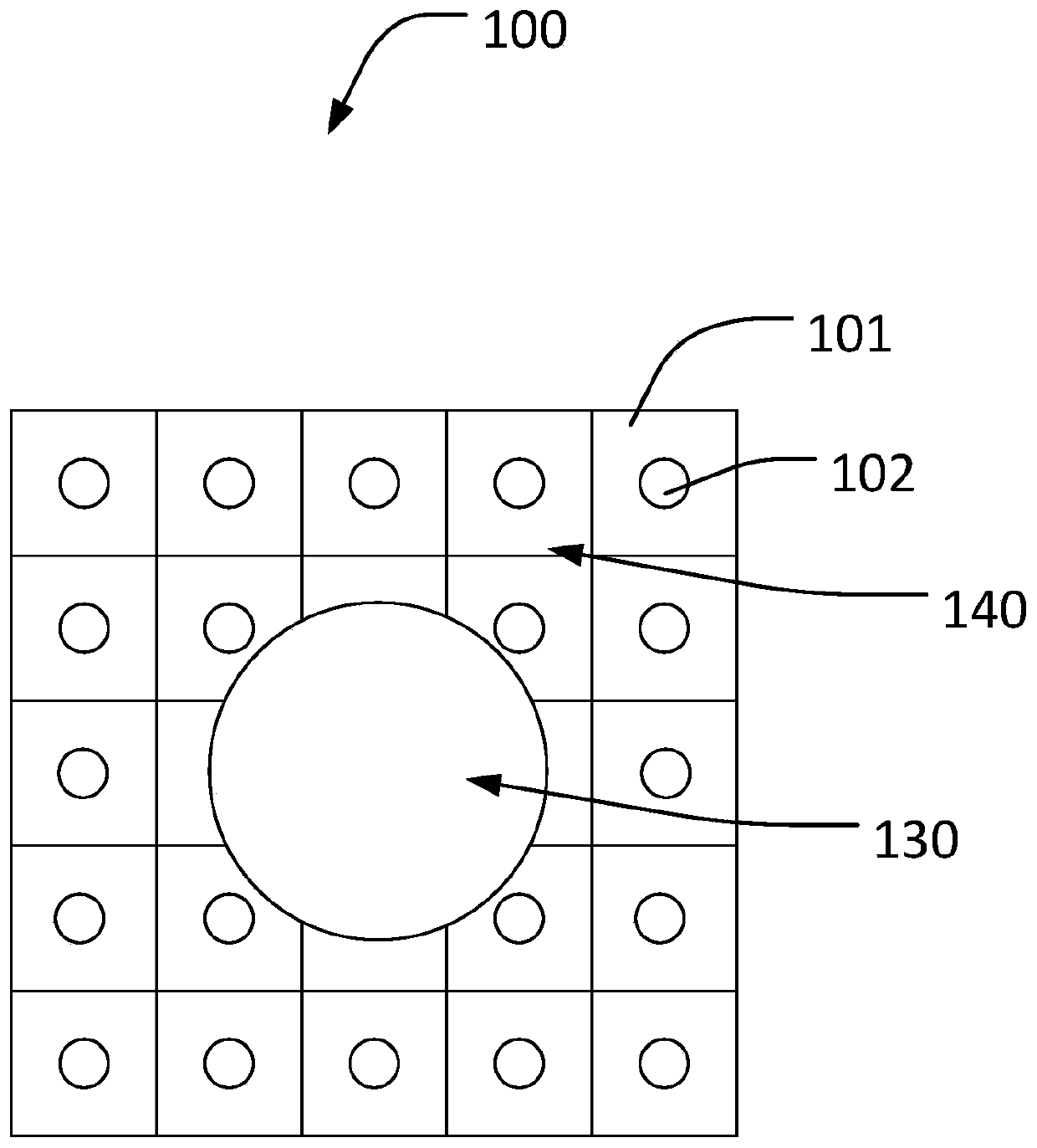
The invention provides a backlight module and a display device. The backlight module comprises a camera area and a backlight area. The backlight area surrounds the camera area. The camera area comprises a transparent irradiation area and a non-transparent irradiation area, wherein the non-transparent irradiation area surrounds the transparent irradiation area. The non-transparent irradiation areais provided with a lamp panel; and the lamp panel is provided with at least one lamp bead. Under a display mode, the camera area obtains a uniform light source to realize normal display of the cameraarea under the display mode of the display device, thereby realizing true 100% screen-to-body ratio; and under a lighting mode of a camera module, a light source of the lamp bead is turned off to prevent influence on lighting of the camera module.

Description

technical field [0001] The invention relates to the display field, in particular to a backlight module and a transparent display device. Background technique [0002] With the innovation and development of display technology, high-screen-to-body ratio screens have become the mainstream trend in the application of new-generation terminal equipment. Due to the lighting requirements of some functional devices in terminal equipment, such as cameras and light sensors, the screen-to-body ratio of display screens is difficult. Improvement, a transparent display device that takes into account both lighting and display becomes the best choice to meet this demand. However, in the application of terminal equipment, the transparent display device cannot use the traditional backlight source and external light as the light source of the display mode. [0003] Therefore, it is necessary to propose a new backlight module and transparent display device to increase the screen-to-body ratio o...

Claims


Application Information

Patent Timeline
Patent Type & Authority Applications(China)
IPC IPC(8): G02F1/13357G09F9/33
CPCG09F9/33G02F1/133603G02F1/133615G02F1/13312G02F1/1336H04M1/0264H04M1/0266G02B6/0011H04N23/56G03B15/02H04N23/00
Inventor 梅新东侯少军王超刘广辉
Owner WUHAN CHINA STAR OPTOELECTRONICS TECH CO LTD
Why Eureka
Eureka Blog
Learn More