Optical imaging lens and electronic equipment

An optical imaging lens and optical technology, applied in the direction of optics, optical components, instruments, etc., can solve the problems of difficulty in meeting the height limit requirements and large size of the lens module, and achieve the effect of low module size and overall height reduction

Pending Publication Date: 2019-08-09
ZHEJIANG SUNNY OPTICAL CO LTD
View PDF0 Cites 7 Cited by
  • Summary
  • Abstract
  • Description
  • Claims
  • Application Information

AI Technical Summary

Problems solved by technology

In this case, the height of the lens increases. Even if the lens is reduced by prism steering, the size of the lens in the Y-axis direction will still be relatively large, and it is difficult to meet the height limit requirements of the lens module.

Method used


Image

  • Optical imaging lens and electronic equipment
  • Optical imaging lens and electronic equipment
  • Optical imaging lens and electronic equipment

Examples


Embodiment 1

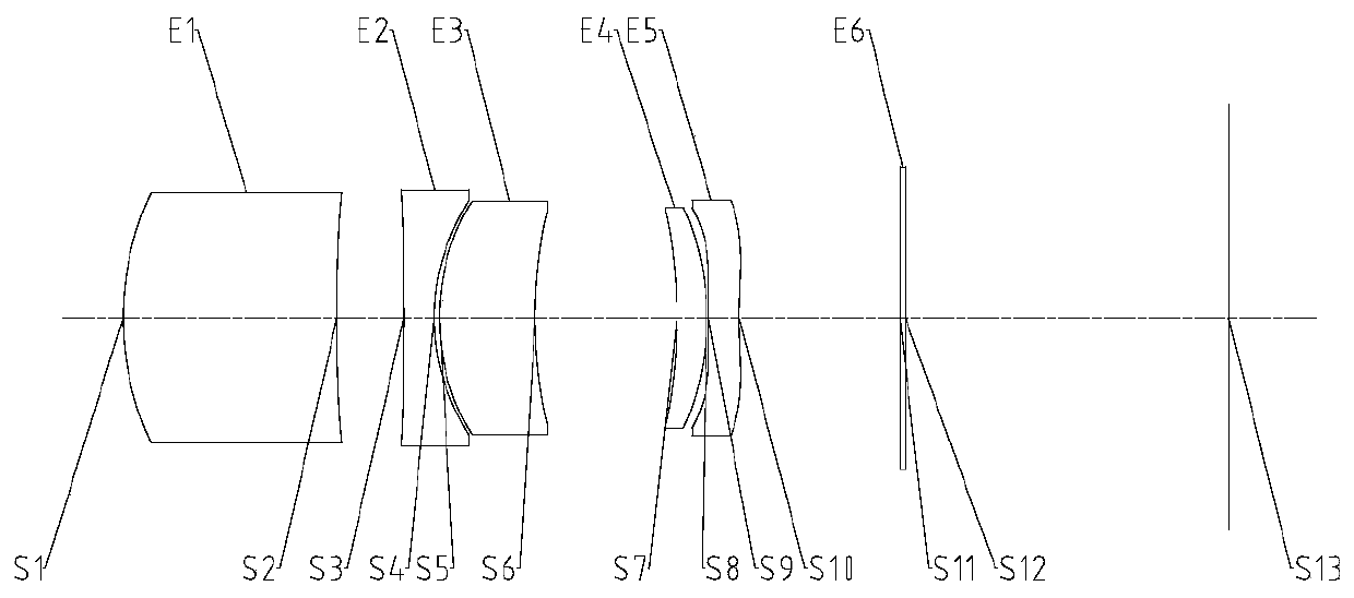
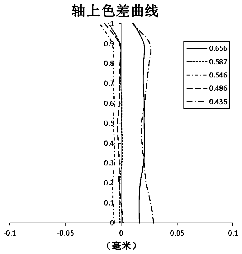
[0063] Refer to the following Figure 2 to Figure 3C An optical imaging lens according to Embodiment 1 of the present application is described. figure 2 is a schematic structural view showing the optical imaging lens according to Embodiment 1 of the present application.

[0064] like figure 2 As shown, the optical imaging lens includes in sequence from the object side to the image side along the optical axis: a first lens E1, a second lens E2, a third lens E3, a fourth lens E4, a fifth lens E5, an optical filter E6 and an imaging lens. Surface S13.

[0065]The first lens E1 has positive refractive power, its object side S1 is convex, and its image side S2 is concave. The second lens E2 has negative refractive power, its object side S3 is concave, and its image side S4 is concave. The third lens E3 has positive refractive power, its object side S5 is convex, and its image side S6 is concave. The fourth lens E4 has positive refractive power, its object side S7 is concave,...

Embodiment 2

[0077] Refer to the following Figure 4 to Figure 5C An optical imaging lens according to Embodiment 2 of the present application is described. Figure 4 A schematic structural diagram of an optical imaging lens according to Embodiment 2 of the present application is shown.

[0078] like Figure 4 As shown, the optical imaging lens includes in sequence from the object side to the image side along the optical axis: a first lens E1, a second lens E2, a third lens E3, a fourth lens E4, a fifth lens E5, a sixth lens E6, a filter Light sheet E7 and imaging surface S15.

[0079] The first lens E1 has positive refractive power, its object side S1 is convex, and its image side S2 is convex. The second lens E2 has negative refractive power, its object side S3 is concave, and its image side S4 is concave. The third lens E3 has positive refractive power, its object side S5 is convex, and its image side S6 is concave. The fourth lens E4 has positive refractive power, its object side ...

Embodiment 3

[0088] Refer to the following Figure 6 to Figure 7C An optical imaging lens according to Embodiment 3 of the present application is described. Image 6 A schematic structural diagram of an optical imaging lens according to Embodiment 3 of the present application is shown.

[0089] like Image 6 As shown, the optical imaging lens includes in sequence from the object side to the image side along the optical axis: a first lens E1, a second lens E2, a third lens E3, a fourth lens E4, a fifth lens E5, a sixth lens E6, a filter Light sheet E7 and imaging surface S15.

[0090] The first lens E1 has positive refractive power, its object side S1 is convex, and its image side S2 is convex. The second lens E2 has negative refractive power, its object side S3 is convex, and its image side S4 is concave. The third lens E3 has negative refractive power, its object side S5 is convex, and its image side S6 is concave. The fourth lens E4 has positive refractive power, its object side S7 ...


PUM


Abstract

The invention provides an optical imaging lens and electronic equipment. The optical imaging lens successively includes a first lens with focal power, a second lens with the focal power, a third lenswith the focal power and more than two follow-up lens with the focal power in a light axis direction from the object side to the image side; and the distance TTL on the light axis between the object face of the first lens and the imaging face of the optical imaging lens and the total effective focal length f of the optical imaging lens are satisfied: TTL / f is less than 1 and an opticator of more than one lens in lens included by the optical imaging lens is cut on the Y axe, the largest effective radius DY on the Y axe of a cut lens and the largest effective radius DX on the X axe are satisfiedthat DY / DX is greater than 0.5 and less than 1.0, and the X axe is perpendicular to the Y axe.

Description

technical field [0001] The embodiments of the present application relate to the field of optical elements, and in particular, relate to an optical imaging lens and an electronic device. Background technique [0002] Generally, the ultra-telephoto optical imaging lens needs to obtain sufficient luminous flux (that is, a large aperture) due to its long focal length. Therefore, not only the TTL of the entire lens will become longer, but the diameter of the entrance pupil of the lens will also become larger. In this case, the height of the lens increases. Even if the lens is reduced by prism steering, the size of the lens in the Y-axis direction will still be relatively large, which is difficult to meet the height limit requirements of the lens module. Contents of the invention [0003] Aiming at the technical problems existing in the prior art, the present application provides an optical imaging lens and electronic equipment. [0004] One aspect of the present application p...

Claims


Application Information

Patent Timeline
Patent Type & Authority Applications(China)
IPC IPC(8): G02B13/00G02B13/18
CPCG02B13/0045G02B9/60G02B13/02
Inventor 黄林戴付建赵烈烽
Owner ZHEJIANG SUNNY OPTICAL CO LTD
Why Eureka
Try Eureka