Gear synchronous quenching device

A technology of quenching device and gear, applied in the direction of quenching device, furnace type, furnace, etc., can solve the problems of low efficiency, fracture, large deformation of workpiece, etc., and achieve the effect of ensuring heating

Pending Publication Date: 2019-08-20
西安北辰亿科电子科技有限公司
View PDF0 Cites 6 Cited by
  • Summary
  • Abstract
  • Description
  • Claims
  • Application Information

AI Technical Summary

Problems solved by technology

The traditional quenching method is quenching in a carburizing furnace, but due to the long interval between heating and quenching, it often causes large deformation of the workpiece and affects the transmission efficiency of the gear
Moreover, the traditional method consumes a lot of energy and costs high, and the efficiency is low
This treatment method is also easy to increase the residual stress on the root tooth surface, resulting in the occurrence of fracture, so it cannot achieve a satisfactory treatment effect

Method used


Image

  • Gear synchronous quenching device
  • Gear synchronous quenching device
  • Gear synchronous quenching device

Examples


Embodiment Construction

[0026] Below in conjunction with accompanying drawing, the present invention is described in further detail:

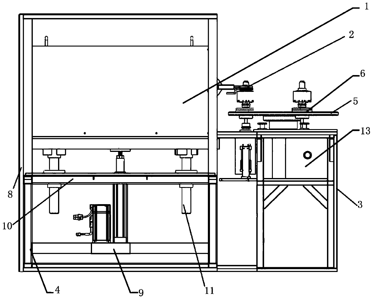
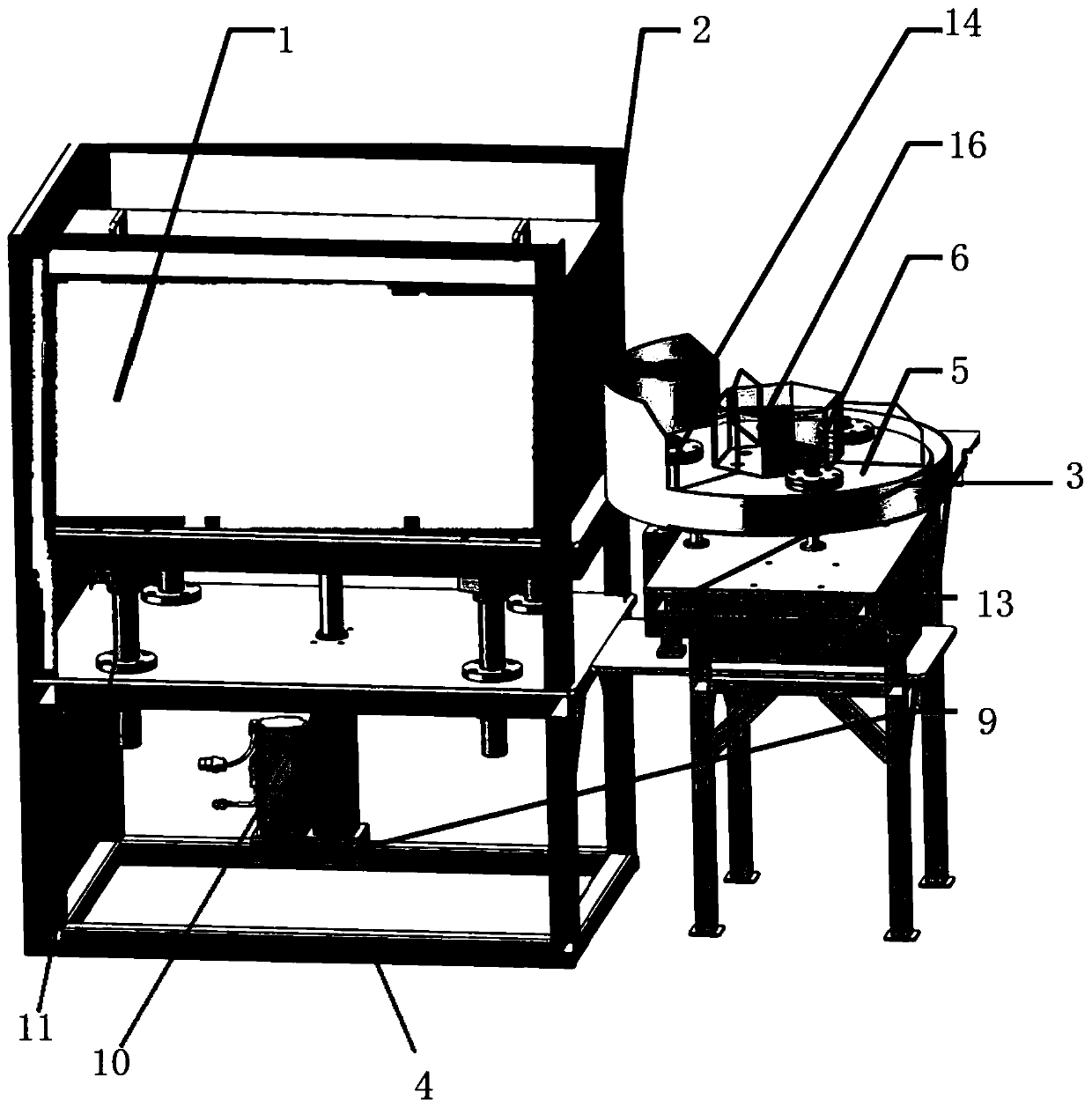
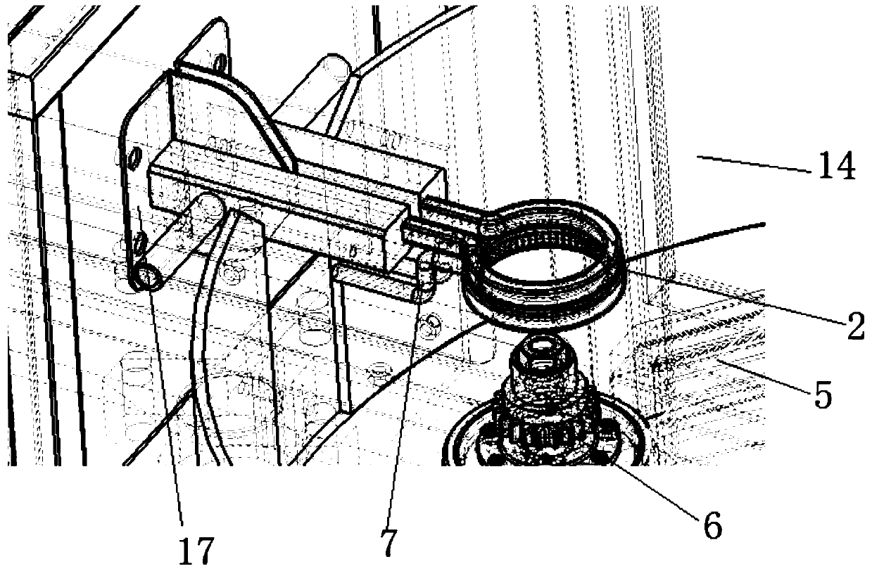
[0027] like Figure 1 to Figure 4 As shown, a gear synchronous quenching device includes a quenching power supply extension 1, an annular inductor 2 and a clamping tool 3 for clamping the gear to be quenched, and the annular inductor 2 is fixed on the quenching power supply extension 1 and the quenching power supply extension 1. Output power connection; the lower end of the quenching power supply extension 1 is provided with a lifting mechanism 4; the lower end of the annular sensor 2 is provided with an annular water shower ring 7, which is fixed on the outer wall of the quenching power supply extension 1; the inner wall of the annular water shower ring 7 is provided with multiple a rain spray nozzle; the annular water spray ring 7 is connected to the quenching liquid source through a pipeline;

[0028] The clamping tool 3 includes a revolution turntable 5 and an au...


PUM


Abstract

The invention discloses a gear synchronous quenching device. The device comprises a quenching power supply extension machine, an annular sensor and a clamping tooling used for clamping to-be-quenchedgears. The annular sensor is fixed to the quenching power supply extension machine and connected with a quenching power supply extension machine output power supply. A lifting mechanism is arranged atthe lower end of the quenching power supply extension machine. An annular water pouring ring is arranged at the lower end of the annular sensor and fixed to the outer wall of the quenching power supply extension machine. A plurality of water pouring nozzles are formed in the inner wall of the annular water pouring ring. The clamping tooling comprises a rotating turntable and self-rotating toolingbodies uniformly arranged on the rotating turntable along a rotating turntable rotary shaft. The to-be-measured gears are mounted on the self-rotating tooling bodies correspondingly and driven by theself-rotating tooling bodies to rotate. The to-be-measured gears are heated uniformly through heating of the annular sensor, residual stress produced due to non-uniform heating of the to-be-measuredgears is prevented, meanwhile, the to-be-measured gears are quenched by means of the annular water pouring ring, quenching can be performed in time, deformation produced because of the long time duration between part heating and quenching, and the gear synchronous quenching device is simple in structure and can be used for greatly improving the gear quenching efficiency.

Description

technical field [0001] The invention belongs to the technical field of induction heating, in particular to a gear synchronous quenching device. Background technique [0002] Gear is a widely used transmission part. The working mode of intermeshing for transmission requires the gear to have the characteristics of shock resistance, vibration and noise as small as possible, high strength, good wear resistance and long life. Therefore, in the production process of gears, the surface profile of gears needs to be heat treated to improve its strength and wear resistance. The traditional quenching method is quenching in a carburizing furnace, but due to the long interval between heating and quenching, it often causes large deformation of the workpiece and affects the transmission efficiency of the gear. In addition, the traditional method has high energy consumption, high cost and low efficiency. This treatment method also tends to increase residual stress on the root tooth surfac...

Claims


Application Information

Patent Timeline
Patent Type & Authority Applications(China)
IPC IPC(8): C21D1/10C21D1/667C21D9/32
CPCC21D1/10C21D1/667C21D9/32Y02P10/25
Inventor 常宏苏一超尚雅层来跃深孙凯东刘长可韩东辰郭瑶
Owner 西安北辰亿科电子科技有限公司
Why Eureka
Try Eureka