
Bundle bale propelling device for biomass bale fuel boiler
A propulsion device and biomass technology, applied in the field of boilers, can solve the problems that biomass cannot be bundled and pushed, occupying the platform space in front of the boiler, etc., and achieve the effect of not easy to break down, convenient maintenance, and reasonable propulsion
- Summary
- Abstract
- Description
- Claims
- Application Information
AI Technical Summary
Problems solved by technology
Method used
Image

Examples
Embodiment 1
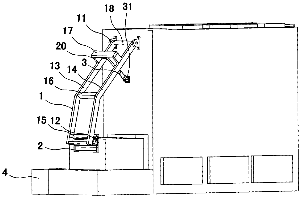
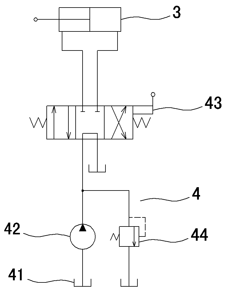
[0009] Embodiment one, such as figure 1 , figure 2 As shown, it includes a bale push swing frame 1, a bale push frame 2, a push hydraulic cylinder 3 and a hydraulic pump station 4, and the left and right sides of the upper part of the bale push swing frame 1 are respectively provided with hinges for pushing the bale push swing frame 1. The hinge seat 11 on the upper side of the front wall of the boiler makes the lower part of the bale pushing swing frame 1 swing back and forth away from and towards the furnace door below the boiler front wall, and the bale pushing frame 2 is located at the lower part of the bale pushing swing frame 1 facing the boiler In the direction of the furnace door, the left and right sides of the bale pushing rack 2 are respectively hinged on the bale pushing swing frame 1 through the hinge seats 2 12 installed on the left and right sides of the lower part of the bale pushing swing frame 1, so that the bale pushing rack 2 pushes When it reaches the fr...
Embodiment 2
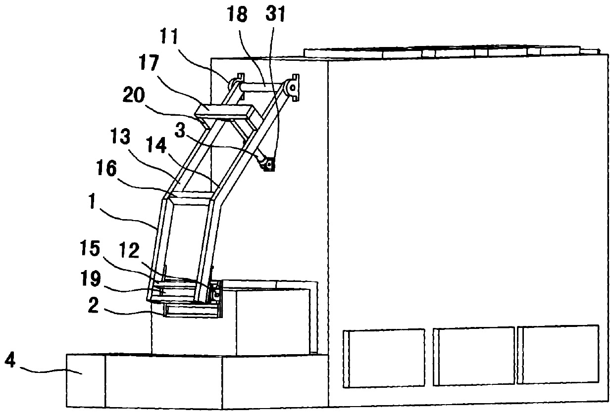
[0014] Embodiment two, such as image 3 As shown, the difference from Embodiment 1 is that the lower part of the bale pushing swing frame 1 facing the boiler furnace door is provided with an automatic sliding mechanism installed on the bale pushing swing frame 1 along the vertical extension direction of the bale push swing frame 1. Slide frame 19, each hinge seat 2 12 is respectively installed on the left and right sides of automatic slide frame 19, and bundle pushing frame 2 is hinged on the automatic slide frame 19 by each hinge seat 2 12, and bundle pushes swing frame 1 when tying The bale pusher 2 automatically slides up and down on the bale pusher 1 to adjust the position to prevent the bale pusher 2 and the bale from moving up and down.
[0015] Method of use: when in use, the hydraulic distributor 43 is used to control the expansion and contraction of the propulsion hydraulic cylinder 3, and the expansion and contraction of the propulsion hydraulic cylinder 3 drives the...
PUM
 Abstract
Description
Claims
Application Information