
Slidable lifting auxiliary device

A technology of auxiliary devices and slides, which is applied in the direction of lifting devices, lift frames, etc., can solve the problems of inability to adjust the relative position, difficulty in lifting large switch mechanisms, etc.

Pending Publication Date: 2019-09-13
GUANGDONG POWER GRID CO LTD +1
View PDF0 Cites 0 Cited by
  • Summary
  • Abstract
  • Description
  • Claims
  • Application Information

AI Technical Summary

Problems solved by technology

[0003] The present invention provides a slidable lifting auxiliary device in order to overcome the defect that the large switch mechanism is difficult to lift in the prior art and the relative position cannot be adjusted during lifting.

Method used


Image

  • Slidable lifting auxiliary device

Examples


Embodiment 1

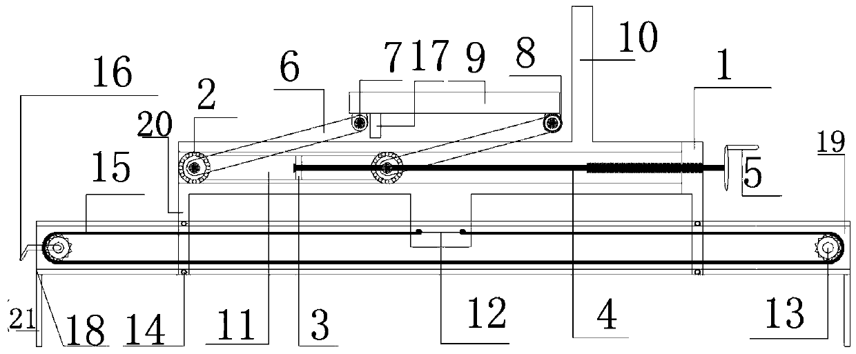
[0030] A slideable lifting aid such as figure 1 As shown, it includes frame body 1, rotating bearing 2, intermediate connecting plate 3, screw rod 4, transmission rod 6, hinge bolt 7, plane bearing 8, supporting platform 9, baffle plate 10, side connecting plate 11, supporting platform 19 ;

[0031] The baffle plate 10 is connected to the top of the frame body 1;

[0032] The inside of the frame body 1 is provided with a concave slideway 18, and at the same time, both sides of the frame body 1 are provided with side connecting plates 11, and the side connecting plates 11 are connected through the middle connecting plate 3. All are provided with a rotating bearing 2, and the rotating bearing 2 is fitted and connected with the concave-shaped slideway 18, and the rotating bearing 2 is used to convert plane friction into sliding friction and reduce friction in the lifting process.

[0033] The side connecting plates 11 are connected by the middle connecting plate 3, so that both...


PUM


Abstract

The invention relates to a slidable lifting auxiliary device. The slidable lifting auxiliary device comprises a frame body (1), a rotating bearing (2), a middle connecting plate (3), a screw rod (4),a transmission rod (6), a hinging bolt (7), a plane bearing (8), a supporting platform (9), a baffle plate (10), a side face connecting plate (11) and a supporting platform (19), the screw rod (4) arranged in the frame body (1) drives the middle connecting plate (3), the middle connecting plate (3) drives the rotating bearing (2), the rotating bearing (2) is used for stably lifting the supportingplatform (9) through the transmission rod (6), so that lifting of a large-scale switch mechanism is realized, fixing gears (13) in the supporting platform (19) at the lower portion of the device rotate to drive a chain (15), then the chain (15) drives the frame body (1) to move stably so that the relative position of the large-scale switch mechanism can be slidably adjusted. According to the slidable lifting auxiliary device, the technical defects that in the case of the large-scale switch mechanism, lifting difficulty is large, and the relative position can not be slidably adjusted are overcome.

Description

technical field [0001] The invention relates to the field of substation maintenance devices, more specifically, to a slidable lifting auxiliary device. Background technique [0002] When electric maintenance personnel reinstall the heavy cabinet mechanism, due to the heavy structural weight of the switch mechanism and it is not easy to lift, the maintenance personnel often need to use sleepers or workbenches for secondary lifting or use Manpower lifts and propels, and the traditional lifting tool cannot slide and adjust the relative position of the object to be lifted according to the actual installation position when lifting. The traditional lifting method is difficult and dangerous, and it is very easy for maintenance personnel to use improper force. Accidents result in equipment damage and personal injury. Contents of the invention [0003] The present invention provides a slidable lifting auxiliary device in order to overcome the defects in the prior art that it is di...

Claims


Application Information

Patent Timeline
Patent Type & Authority Applications(China)
IPC IPC(8): B66F7/06B66F7/28
CPCB66F7/0608B66F7/0641B66F7/28
Inventor 罗宗杰王晓明胡浩莹易水平刘义杰吴冠占志峰周艳伟李海平刘建明郑小慧喻凌立许超尧廖颖欢陈臻刘水根刘丽陈文杰庄骞张斌叶鹏运傅智浩黄崇斌余光海陈玉华陈婷陈燕丽张丽丽于文辉庞秋明李静朱秋霖林仲卿赵志刚黄锐杰王英李振宇廖立辉蔡振华曹维安黎卡黄嘉瑜黄强张家福
Owner GUANGDONG POWER GRID CO LTD
Learn More