Check patentability & draft patents in minutes with Patsnap Eureka AI!

Method and device for imaging objects by optical neutron transmission

一种中子、成像的技术,应用在中子辐射的测量、测量装置、辐射的测量等方向,能够解决光中子透射图像分辨率变差等问题,达到解决分别率下降的效果

Active Publication Date: 2021-07-09
NUCTECH CO LTD
View PDF7 Cites 0 Cited by
  • Summary
  • Abstract
  • Description
  • Claims
  • Application Information

AI Technical Summary

Problems solved by technology

For the aforementioned reasons, such as figure 1 As shown, the resolution of the optical neutron transmission image becomes worse relative to the X-ray transmission image

Method used


Image

  • Method and device for imaging objects by optical neutron transmission
  • Method and device for imaging objects by optical neutron transmission
  • Method and device for imaging objects by optical neutron transmission

Examples


Embodiment Construction

[0035] Hereinafter, the present invention will be described with reference to the drawings.

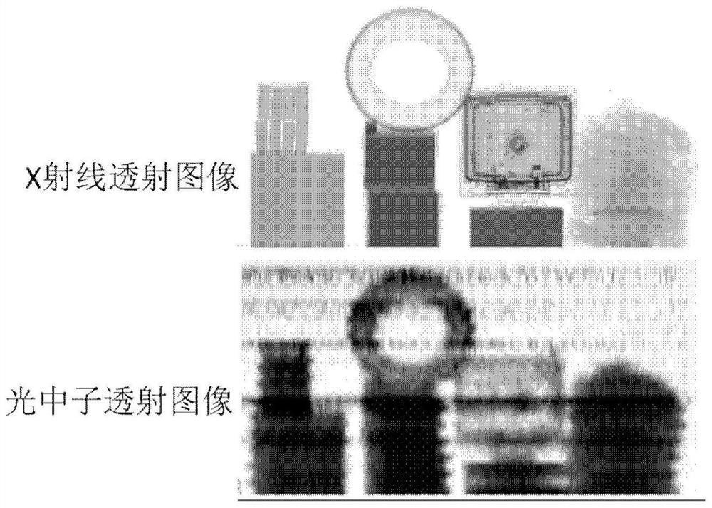
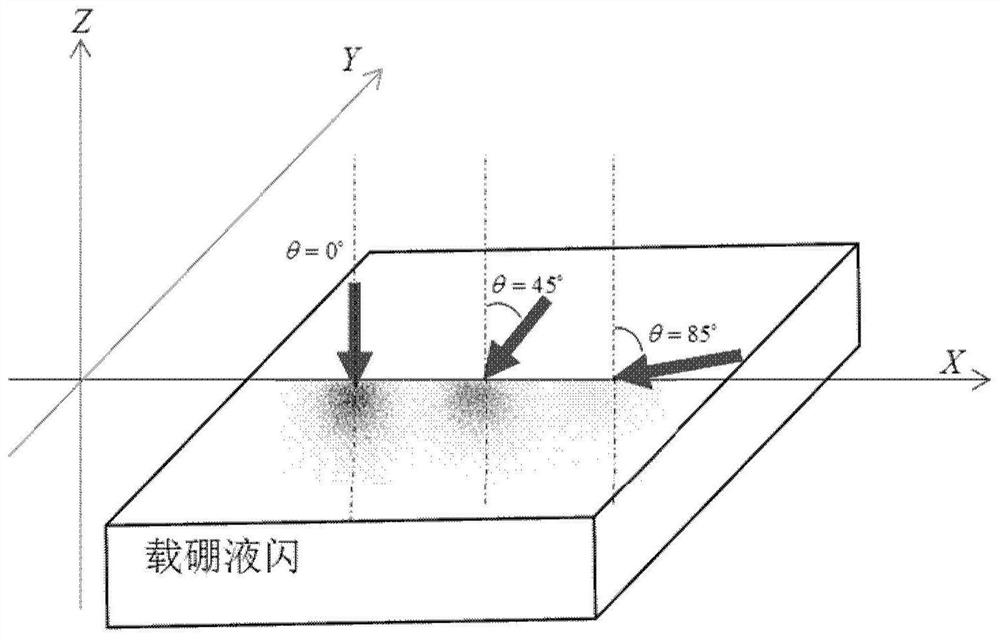
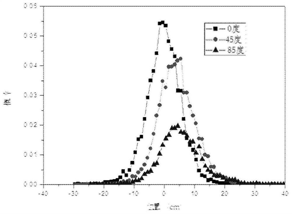
[0036] First, the technical premise of the present invention will be described. When the energy of neutrons is not very high (that is, several MeV or lower, the energy of optical neutrons meets this energy range), the elastic scattering of neutrons with protons mainly manifests as S-wave collisions. In the center-of-mass system, the directions of scattered neutrons caused by S-wave collisions are isotropic. Therefore, after one collision, it can basically be considered that neutrons have lost their "memory" of the direction of incidence. Therefore, it can be approximately considered that no matter how neutrons are incident on the surface of a moderator, their scattering process in the moderator is approximately the same. figure 2 is the distribution map of the absorption positions of neutrons incident from different angles in boron-carrying liquid flash. exist figure 2 Three dif...


PUM


Abstract

The invention provides a method and a device for imaging an object by using light neutron transmission. The method includes: using an optical neutron source to emit optical neutron rays and irradiating the inspected object; using a detector to receive the optical neutron rays from the optical neutron source; Photoneutron rays image the object under inspection. The detector is a detector capable of slowing down photoneutrons and absorbing photoneutrons. The angle formed by the line directions is in the range of 60° to 87°.

Description

technical field [0001] The invention relates to a transmission imaging technology, in particular to a method and device for imaging an object by using light neutron transmission. Background technique [0002] When using the optical neutron source generated by the linear electron accelerator for transmission imaging, the interference problem of X-ray pulses on the detection of optical neutrons must be solved first, because optical neutrons are the companions of X-rays, and the intensity of the latter is much greater than that of the former (about 4 to 5 orders of magnitude larger), therefore, even if a certain detector is very sensitive to neutrons and quite insensitive to photons, the signal amplitude of the X-ray pulse will still obviously exceed the signal amplitude of the optical neutron pulse, The transmission imaging information obtained at this time mainly comes from the contribution of X-ray pulses rather than the contribution of photoneutrons. [0003] Therefore, in...

Claims


Application Information

Patent Timeline
Patent Type & Authority Patents(China)
IPC IPC(8): G01N23/05G01N23/09G01T3/02G01T3/06
CPCG01N23/05
Inventor 杨祎罡张勤俭李元景张智
Owner NUCTECH CO LTD
Features
  • R&D
  • Intellectual Property
  • Life Sciences
  • Materials
  • Tech Scout
  • Unparalleled Data Quality
  • Higher Quality Content
  • 60% Fewer Hallucinations
Learn More