Antifatigue torsion beam formed through pipe punching

A stamping forming and anti-fatigue technology, applied in the field of automobile parts, can solve the problems such as the need to improve the anti-fatigue ability of the beam, the deformation of the side wall of the pipe, and the easy fracture of the beam, so as to improve the operation stability, prevent cracking, and improve the anti-fatigue ability. Effect

Pending Publication Date: 2019-10-29
天人汽车底盘(芜湖)股份有限公司
View PDF2 Cites 1 Cited by
  • Summary
  • Abstract
  • Description
  • Claims
  • Application Information

AI Technical Summary

Problems solved by technology

However, the processing method of controlled stamping molding in the prior art mainly has the following disadvantages: when the pipe is directly stamped on the mold, because the inside of the pipe is a hollow structure, the stamping head is directly punched down, and the impact force on the pipe is relatively large, and due to The inside of the pipe is hollow, and there is no support on the side wall of the pipe in contact with the stamping head, so that the side wall of the pipe being punched has no buffer, and the side wall of the pipe will undergo a large deformation in a short time, which is prone to small cracks. For a long time, when the beam is used on the car, the beam is easy to break, and the fatigue resistance of the beam needs to be improved

Method used


Image

  • Antifatigue torsion beam formed through pipe punching
  • Antifatigue torsion beam formed through pipe punching
  • Antifatigue torsion beam formed through pipe punching

Examples


Embodiment 1

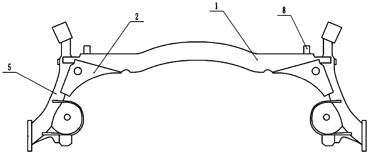
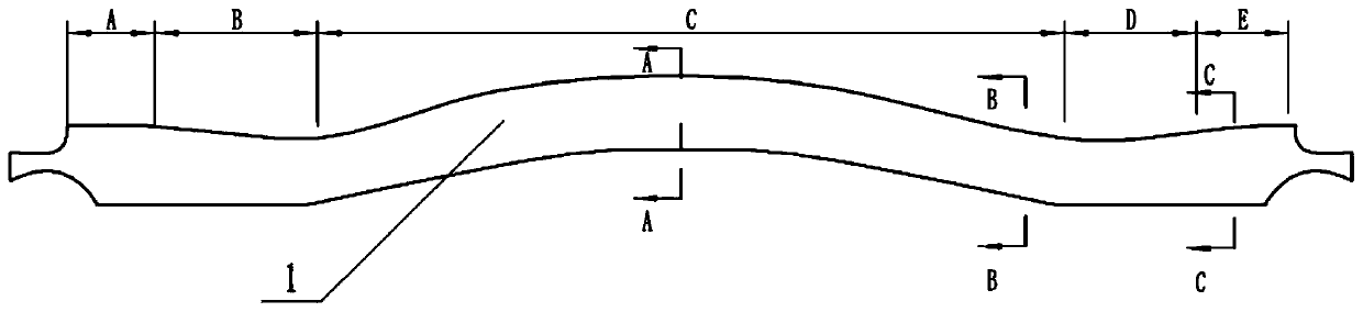
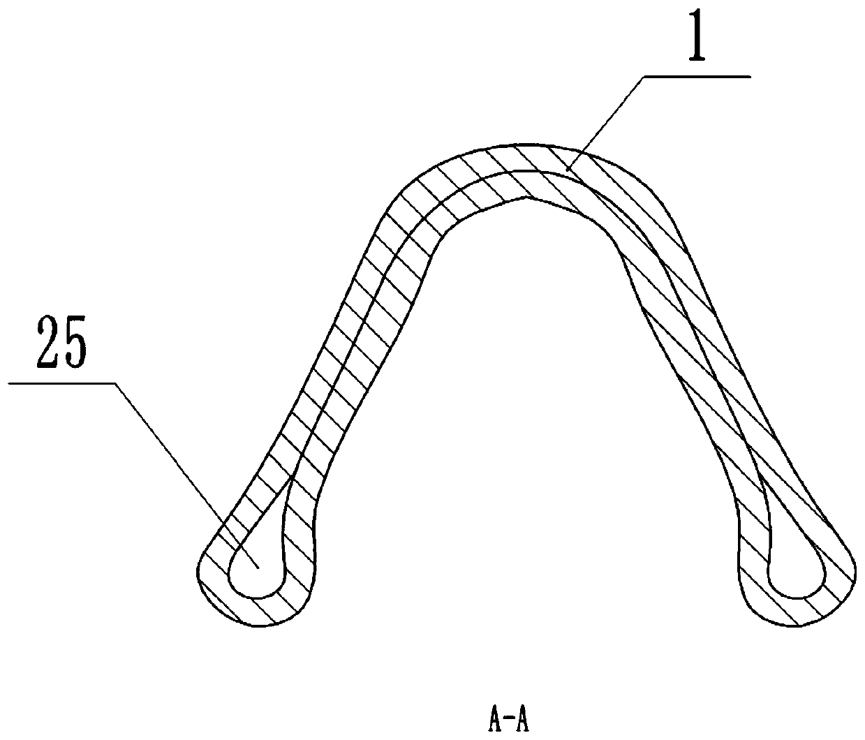
[0033] Basic as attached figure 1 As shown: the anti-fatigue torsion beam formed by control stamping, including the beam 1 and the longitudinal arm 5, the longitudinal arm 5 is welded to the two ends of the beam 1, specifically, the two ends of the beam 1 are provided with interfaces, combined with figure 2 As shown, the edges of the joints at both ends of the crossbeam 1 are recessed toward the middle of the crossbeam 1, so that the joints at both ends of the crossbeam 1 can wrap the outer wall of the longitudinal arm 5 because the shape of the joint is arc-shaped, so that the longitudinal arm 5 is welded on the crossbeam 1 It is relatively smooth and smooth, and the welding strength of the longitudinal arm 5 and the beam 1 can also be improved.

[0034] One end of the trailing arm 5 is provided with a sleeve, and the other end of the trailing arm 5 is provided with a hub seat. The end of the longitudinal arm 5 close to the hub seat is provided with a spring seat, which is ...

Embodiment 2

[0048] combine Figure 8 As shown, the beam 1 is fixed with an illumination mechanism 9 . Specifically, combine Figure 9 As shown, the lighting mechanism 9 includes a base plate 10 welded on the beam 1, a lighting lamp 14 located on the base plate 10, and a protective cover 11 for covering the lighting lamp 14, and the protective cover 11 can be snapped through a clamp block and a slot Covered on the bottom plate 10 in a way. combine Figure 10 As shown, the central position of the bottom of the base plate 10 is provided with a hinged hole 19, and the surrounding of the hinged hole 19 is provided with annularly distributed support holes 18. The number of rings of the support holes 18 in this embodiment is two rings, and the support holes of the inner ring The number of 18 is six, the number of supporting holes 18 of the outer ring is ten, and the insides of the supporting holes 18 are all bonded with magnets. combine Figure 9 As shown, the protective cover 11 is provide...


PUM


Abstract

The invention relates to the field of vehicle parts, in particular to an antifatigue torsion beam formed through pipe punching. The antifatigue torsion beam comprises a cross beam and trailing arms, the trailing arms are fixedly connected to the two ends of the cross beam, and the cross beam is formed through punching of a pipe. Before the pipe is punched, the pipe is filled with wax, and the waxis in a honeycomb shape. According to the scheme, the antifatigue capability of the torsion beam is improved.

Description

technical field [0001] The invention relates to the field of auto parts, in particular to an anti-fatigue torsion beam formed by control stamping. Background technique [0002] The torsion beam is an important part of the automobile. During the operation of the automobile, it plays an important role in the shock absorption of the automobile, the transmission of loads, the reduction of the shaking of the vehicle, the provision of suitable freedom of movement for the wheels, and the assurance of the stability of the car body. to an important role. [0003] The torsion beam usually includes a crossbeam and a longitudinal arm. The longitudinal arm is welded at both ends of the crossbeam. During the operation of the car, the welding position of the longitudinal arm and the crossbeam is prone to breakage because the load of the car will change irregularly and irregularly. , so the life of the torsion beam is shorter, and the subsequent maintenance cost is relatively high. [000...

Claims


Application Information

Patent Timeline
Patent Type & Authority Applications(China)
IPC IPC(8): B60G21/05
CPCB60G21/051B60G2206/20B60G2206/8102
Inventor 龚量亮
Owner 天人汽车底盘(芜湖)股份有限公司
Why Eureka
Try Eureka