A suction muffler applied to a compressor

A muffler and compressor technology, applied in the field of compressors, can solve the problems of reducing suction pulsation, failing to eliminate noise, and reducing the cooling capacity of the compressor, so as to reduce suction noise and suction pulsation, and ensure suction. Airtightness and the effect of reducing the amount of lubricating oil

Active Publication Date: 2021-06-08
CHANGHONG HUAYI COMPRESSOR CO LTD
View PDF9 Cites 0 Cited by
  • Summary
  • Abstract
  • Description
  • Claims
  • Application Information

AI Technical Summary

Problems solved by technology

There are two defects in this structure. One is that during the transportation of the compressor and the moment the compressor starts and stops, the movement and the casing will collide, and the buckle fixing the air outlet of the muffler is easy to loosen, resulting in the air outlet of the muffler being sealed with the valve plate. If it is not strict, it will lead to the failure of the suction muffler, which will not achieve the effect of eliminating noise and reducing the suction pulsation. At the same time, it will also reduce the suction efficiency of the compressor and reduce the cooling capacity of the compressor. In addition, the lubricant mixed in the gaseous refrigerant The oil mist will be directly sucked into the cylinder without passing through the muffler, and finally discharged from the compressor through the exhaust channel and enter the refrigeration system, which will reduce the heat exchange efficiency of the refrigeration system and increase the power consumption of the refrigeration system
The second is that there is only a single airflow channel inside the muffler, and the gaseous refrigerant coming out of the muffler is directly sucked into the cylinder. Due to the periodic characteristics of suction and exhaust when the refrigerator compressor is working, suction pulsation occurs, which reduces the suction of the compressor. gas efficiency

Method used


Image

  • A suction muffler applied to a compressor
  • A suction muffler applied to a compressor
  • A suction muffler applied to a compressor

Examples


Embodiment Construction

[0035] Attached below Figure 1-15 The present invention is described in further detail with specific embodiment:

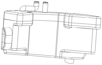
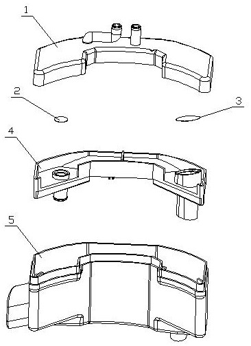
[0036] A suction muffler applied to a compressor, comprising an upper cover 1, a filter screen 1 2, a filter screen 2 3, a middle partition 4 and a casing 5;

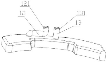
[0037] The top of the upper cover 1 is welded with an outlet pipe 1 12 and an outlet pipe 2 13, the bottom of the upper cover 1 is injection molded with an installation groove 14, and the middle of the upper cover 1 is injection molded with an installation groove 2 15;

[0038] The middle partition 4 includes a wall surface one 41 and a bottom surface one 40, the wall surface one 41 is injection molded on the periphery of the bottom surface one 40, and the bottom surface one 40 is integrally injection-molded by the slope one 43, the slope two 44 and the slope three 45, The middle part of the slope 44 is injection molded with a separation plate 42, and the two ends of the separation plate 42 are injection ...


PUM


Abstract

The invention discloses a suction muffler applied to a compressor, comprising an upper cover (1), a middle partition (4) and a casing (5); the top of the upper cover (1) is provided with an air outlet pipe ( 12) and outlet pipe 2 (13), the bottom of the upper cover (1) is provided with installation groove 1 (14), and the inner middle is provided with installation groove 2 (15); the inside of the middle partition (4) is provided with a separation plate One (42), the bottom is provided with the installation groove three (410); the top of the housing (5) is provided with the installation notch (57), and the inside is provided with the separation plate two (56); the middle partition (4 ) is set in the housing (5), and the installation groove three (410) is matched with the separation plate two (56); the upper cover (1) is set on the middle partition (4) and the top of the housing (5), Groove one (14) cooperates with installation notch (57), and installation groove two (15) cooperates with separation plate one (42). The invention can improve gas transmission efficiency and reduce oil discharge, so it has broad market prospects.

Description

technical field [0001] The invention relates to the technical field of compressors, in particular to a suction muffler applied to compressors. Background technique [0002] In the suction and exhaust structure of the current refrigerator compressor, the suction muffler has only one air outlet, and the air outlet of the muffler is pressed against the air inlet of the valve plate by buckles, and there is only a single air flow channel inside the muffler. There are two defects in this structure. One is that during the transportation of the compressor and the moment the compressor starts and stops, the movement and the shell will collide, and the buckle fixing the air outlet of the muffler is easy to loosen, causing the air outlet of the muffler to be sealed with the valve plate. If it is not strict, it will lead to the failure of the suction muffler, which will not achieve the effect of eliminating noise and reducing the suction pulsation. At the same time, it will also reduce ...

Claims


Application Information

Patent Timeline
Patent Type & Authority Patents(China)
IPC IPC(8): F04B39/00F04B39/16F04B39/04
CPCF04B39/0061F04B39/04F04B39/16
Inventor 卢俊戢金国陈汉章陈永安白玉芳谌强何四发
Owner CHANGHONG HUAYI COMPRESSOR CO LTD
Why Eureka
Try Eureka