Acoustic devices and electronic equipment

一种声学装置、电子设备的技术,应用在声学装置,电子设备领域,能够解决声学系统灵敏度负面作用、损害扬声器单元声学性能、影响扬声器单元使用寿命等问题,达到提升低频灵敏度、降低共振频率、增加等效声顺的效果

Active Publication Date: 2022-03-15
GOERTEK INC
View PDF10 Cites 0 Cited by
  • Summary
  • Abstract
  • Description
  • Claims
  • Application Information

AI Technical Summary

Problems solved by technology

However, there are problems in the above two methods. The first method of adding sound-absorbing materials to the cabinet needs to achieve good sealing and packaging of the sound-absorbing materials. Otherwise, if the sound-absorbing materials enter the speaker unit, it will damage the acoustic performance of the speaker unit and affect the speaker unit. The service life of the second type of passive radiator is adopted. Near the resonant frequency point fp, the passive radiator radiates strongly, and the sound unit almost stops. Therefore, the high-sensitivity design of the passive radiator can be used to realize the acoustic system in the frequency band near fp The local sensitivity is enhanced; but in the frequency band below fp, the phase of the passive radiator and the sound wave of the sounding unit are opposite, the sound waves cancel each other out, and the passive radiator has a negative effect on the sensitivity of the acoustic system
All in all, the passive radiator can only improve the sensitivity of the frequency band near the resonance point, but cannot improve the sensitivity of all low frequency bands.

Method used


Image

  • Acoustic devices and electronic equipment
  • Acoustic devices and electronic equipment
  • Acoustic devices and electronic equipment

Examples


Embodiment 1

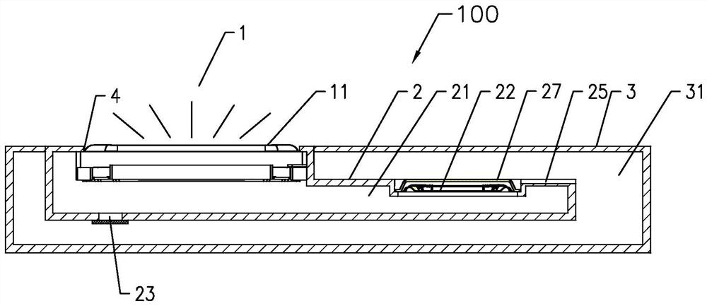
[0050] Such as Figure 3A-Figure 4 As shown, an acoustic device 100 includes a sounding unit 1, wherein, in this embodiment, the sounding unit 1 is a miniature sounding unit, more specifically, the sounding unit 1 is a miniature dynamic speaker. The sound unit 1 generally includes a housing and a vibration system and a magnetic circuit system fixed in the housing. The vibration system includes a vibrating diaphragm 11 fixed on the housing and a voice coil combined with the vibrating diaphragm 11. The magnetic circuit system is formed with The magnetic gap, the voice coil is set in the magnetic gap, and the voice coil reciprocates up and down in the magnetic field after being fed with alternating current, thereby driving the vibrating diaphragm 11 to vibrate and produce sound.

[0051] The acoustic device is provided with a sound outlet 4, and the sound waves on the front side of the vibrating membrane 11 are radiated to the outside through the sound outlet 4, and the sound wav...

Embodiment 2

[0090] The main difference between this embodiment and the above-mentioned embodiments is that in this embodiment, a plurality of sounding units 1 and first airtight chambers 21 are provided in one-to-one correspondence, and a second airtight chamber 31 is provided, and each of the first airtight chambers A flexible deformation part 22 and a protective cover 27 are provided on the cavity wall of the cavity 21 . Specifically, the acoustic device in this embodiment includes two sounding units 1, and two first airtight cavities 21 are respectively designed correspondingly, the second airtight chamber 31 is one, and the cavity walls of the two first airtight cavities 21 A flexible deformation part 22 and a protective cover 27 are respectively designed. This design can facilitate the application in the case of an acoustic device or system that requires multiple sounding units 1 , such as stereophonic or array design requirements.

[0091] In another embodiment, on the cavity wall ...

Embodiment 3

[0093] This embodiment discloses an electronic device 5, such as Figure 7As shown, the acoustic device 100 in the above embodiment is installed on the electronic device 5, which may be a mobile phone, a tablet computer, a notebook, and the like.

[0094] The electronic device 5 specifically includes a casing of the electronic device, and at least a part of the casing of the electronic device is used to form the first airtight cavity 21 and / or the second airtight cavity 31 of the acoustic device. That is, part or all of the cavity wall of the first closed cavity 21 is formed by the casing of the electronic device, or part or all of the cavity wall of the second closed cavity 31 is formed by the casing of the electronic device, or, Part or all of the cavity walls of the first sealed cavity 21 and the second sealed cavity 31 are formed by the casing of the electronic device. In the present invention, the casing of the electronic device doubles as the cavity wall of the first ai...


PUM


Abstract

The invention discloses an acoustic device, comprising: a sounding unit, the sound waves on the front side of the vibrating diaphragm radiate to the outside through the sound outlet; the rear side of the vibrating diaphragm forms a first airtight cavity, and the first airtight cavity A mounting hole is opened on the wall of the cavity, a flexible deformation part is provided on the mounting hole, a second closed cavity is provided outside the first closed cavity, and the flexible deformed part is arranged in the second closed cavity. The sound wave generated during deformation is sealed in the second airtight cavity; a protective cover plate located outside the flexible deformation part is also provided on the installation hole, and the protective cover plate and the flexible deformation part An avoidance space for avoiding the vibration of the flexible deformation part is formed between them; a plurality of air-permeable micro-holes are opened on the protective cover, and the area of ​​each air-permeable micro-hole is less than or equal to 0.2mm 2 . The acoustic device in the present invention can effectively reduce the resonance frequency, and greatly improve the low-frequency sensitivity of the product as a whole.

Description

technical field [0001] The present invention relates to the technical field of acoustics, and more specifically, to an acoustic device and electronic equipment installed with the acoustic device. Background technique [0002] Generally speaking, the acoustic system of the traditional structure (prior art 1) includes a closed box and a sounding unit arranged on the closed box, and a cavity is formed between the closed box and the sounding unit, because the cavity in the acoustic system Due to volume limitations, it is difficult for an acoustic system, especially a small acoustic system, to achieve a satisfactory reproduction of bass. Conventionally, in order to achieve satisfactory bass reproduction in an acoustic system, two methods are usually used. One is to place sound-absorbing materials (such as activated carbon, zeolite, etc.) in the box of the acoustic system for adsorption or desorption. The gas in the body has the effect of increasing the volume and reducing the lo...

Claims


Application Information

Patent Timeline
Patent Type & Authority Patents(China)
IPC IPC(8): H04R1/28
CPCH04R1/2888H04R1/2811H04R1/023H04R1/086H04R1/44H04R2499/11H04R1/021H04R1/2849H04R1/025H04R1/2834H04R9/06
Inventor 陈阿亮陈国强李兆鹏
Owner GOERTEK INC
Why Eureka
Try Eureka