Intelligent drilling method for rail transit shaft part

A technology of rail transit and drilling method, applied in boring/drilling, drilling/drilling equipment, components of boring machine/drilling machine, etc., can solve the problems of time-consuming, low efficiency and labor, and achieve the effect of saving manpower

Active Publication Date: 2019-11-22
湖南华清机械有限公司
View PDF8 Cites 0 Cited by
  • Summary
  • Abstract
  • Description
  • Claims
  • Application Information

AI Technical Summary

Problems solved by technology

Time-consuming, labor

Method used


Image

  • Intelligent drilling method for rail transit shaft part
  • Intelligent drilling method for rail transit shaft part
  • Intelligent drilling method for rail transit shaft part

Examples


Embodiment Construction

[0029] In order to clearly illustrate the technical features of the present solution, the present invention will be described in detail below through specific implementation methods and in conjunction with the accompanying drawings. It should be noted that components illustrated in the figures are not necessarily drawn to scale. Descriptions of well-known components and techniques are omitted herein to avoid unnecessarily limiting the present invention.

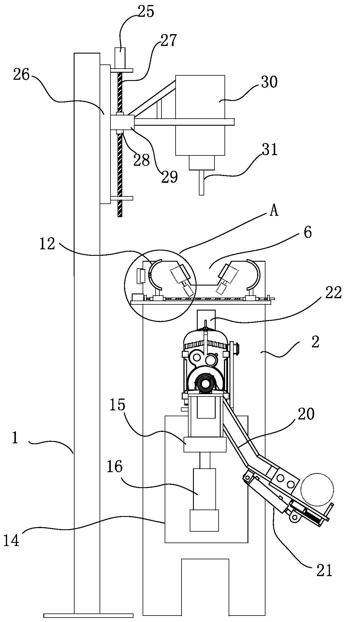
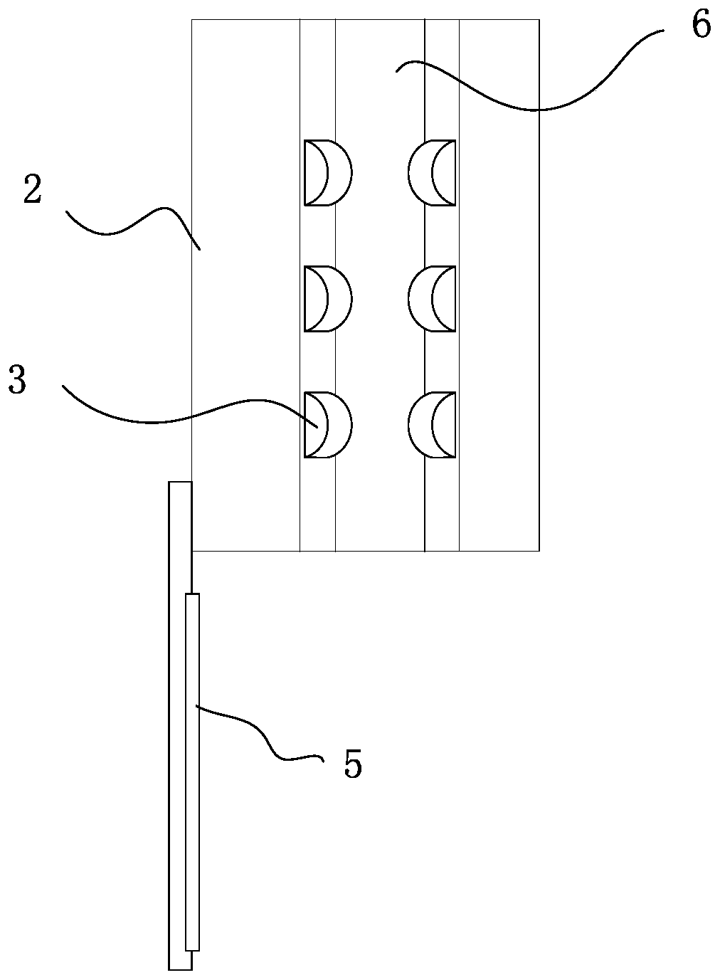
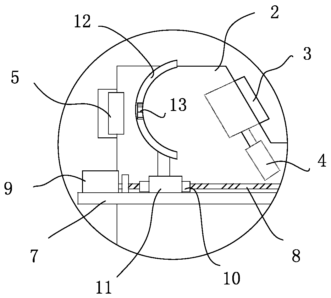
[0030] like Figures 1 to 5 As shown, an intelligent drilling device for rail transit shafts includes a control system and a drill floor mechanism electrically connected to the control system, a clamp mechanism, a reclaiming mechanism, a lifting mechanism and a drilling mechanism. The retrieving mechanism is swingably installed on the drill floor mechanism, and is used to move the processed shaft to the drill floor mechanism, and then remove the shaft from the drill floor mechanism after the shaft is processed. The lifting ...


PUM


Abstract

The invention aims to provide an intelligent drilling method for a rail transit shaft part. The intelligent drilling method is used for solving the technical problem of drilling the rail transit shaftpart. The intelligent drilling method for the rail transit shaft part by utilizing the above device comprises the following steps that S1, the shaft part is placed in a drilling positioning groove ofa drilling machining platform; S2, a drilling screw rod is driven by a drilling lifting driving motor, a drilling nut drives a drilling motor to move downwards, and the drilling motor drills the shaft part through a drilling rod; and after a hole is drilled in the shaft part by the drilling motor, the drilling motor ascends to be separated from the shaft part under the action of the drilling lifting driving motor; S3, under the action of an axial driving motor, axial driving rotating wheels clamp the machined shaft part to move by a certain distance (such as 10 cm) axially; and S4, the step S2 is repeated until the holes in the shaft part are machined, and the machined shaft part is taken down from the drilling positioning groove.

Description

technical field [0001] The invention relates to the technical field of rail transit shaft parts processing, in particular to an intelligent drilling method for rail traffic shaft parts. Background technique [0002] In rail vehicles, due to the need of transmission connection, it is necessary to set multiple holes in the axial direction of some shafts. In the processing method in the prior art, a machine tool is usually used to drill the shaft. After each hole is drilled, the shaft is lifted by a plurality of workers to move a certain distance until the shaft is drilled, and then the shaft is unloaded from the machine tool. Time-consuming, laborious and inefficient. For some heavier shafts, cranes or forklifts are often needed to assist in moving. Contents of the invention [0003] The purpose of the present invention is to provide an intelligent drilling method for rail transit shafts, which is used to solve the technical problem of drilling rail traffic shafts. [00...

Claims


Application Information

Patent Timeline
IPC IPC(8): B23B41/00B23B47/00B23Q3/06B23Q7/00B23Q15/24B23Q17/00B23Q17/22
CPCB23B41/00B23B47/00B23Q3/06B23Q7/00B23Q7/005B23Q15/24B23Q17/006B23Q17/2291
Inventor 韩秀良
Owner 湖南华清机械有限公司
Why Eureka
Try Eureka