Air return box for pre-oxidation furnace and pre-oxidation furnace

The technology of a pre-oxidation furnace and a return air box is applied in the field of oxidation furnace, which can solve the problems affecting the pre-oxidation treatment of fibers, and achieve the effect of sufficient return air and good effect.

Pending Publication Date: 2019-12-17
ZHEJIANG JINGGONG SCI & TECH
View PDF0 Cites 4 Cited by
  • Summary
  • Abstract
  • Description
  • Claims
  • Application Information

AI Technical Summary

Problems solved by technology

[0011] Although the existing air return boxes have high air return efficiency, the gap between adjacent air return boxes tends to cause a small part of hot air not to be sucked by the air return port of the return air box, thus affecting the pre-oxidation treatment of fibers

Method used


Image

  • Air return box for pre-oxidation furnace and pre-oxidation furnace
  • Air return box for pre-oxidation furnace and pre-oxidation furnace
  • Air return box for pre-oxidation furnace and pre-oxidation furnace

Examples


Embodiment 1

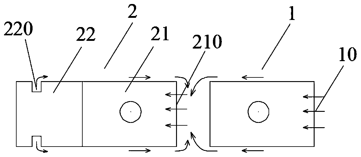
[0044] Such as figure 1 As shown, the return air box for the pre-oxidation furnace of this embodiment is a split design, including a first box 1 and a second box 2 arranged in sequence along the return air direction of the pre-oxidation furnace, the first box 1 and the second box The two boxes 2 are distributed at a preset distance, and the preset distance between the first box 1 and the second box 2 is greater than 60 mm.

[0045] Wherein, the first box body 1 has a first air return port 10 on the side facing the return air direction, which is used to absorb most of the wind in the furnace blowing towards the furnace end, so as to return air through the first box body 1 into the return air duct.

[0046] The second box body 2 includes a return air cavity 21 and a fresh air cavity 22 distributed in sequence along the return air direction of the pre-oxidation furnace. The return air cavity 21 has a second return air port 210 on the side facing the return air direction. 22 has ...

Embodiment 2

[0057] The difference between the air return box for the pre-oxidation furnace of the present embodiment and the first embodiment is:

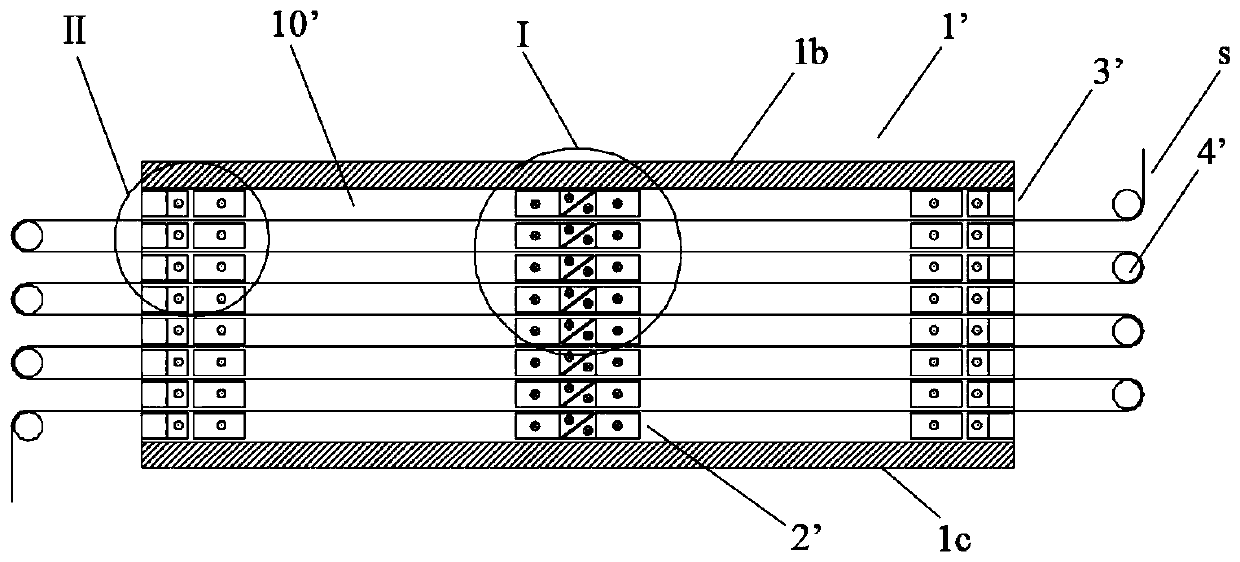
[0058] Such as Figure 9 As shown, the first air return port of the first box body in this embodiment is provided with a first mesh plate 3, and the second air return port of the second box body is provided with a second mesh plate 4. Through the setting of the mesh plate, Improve the uniformity and stability of return air.

[0059] Other structures can refer to Embodiment 1.

[0060] Correspondingly, the differences between the air return box for the pre-oxidation furnace of the present embodiment and the first embodiment are:

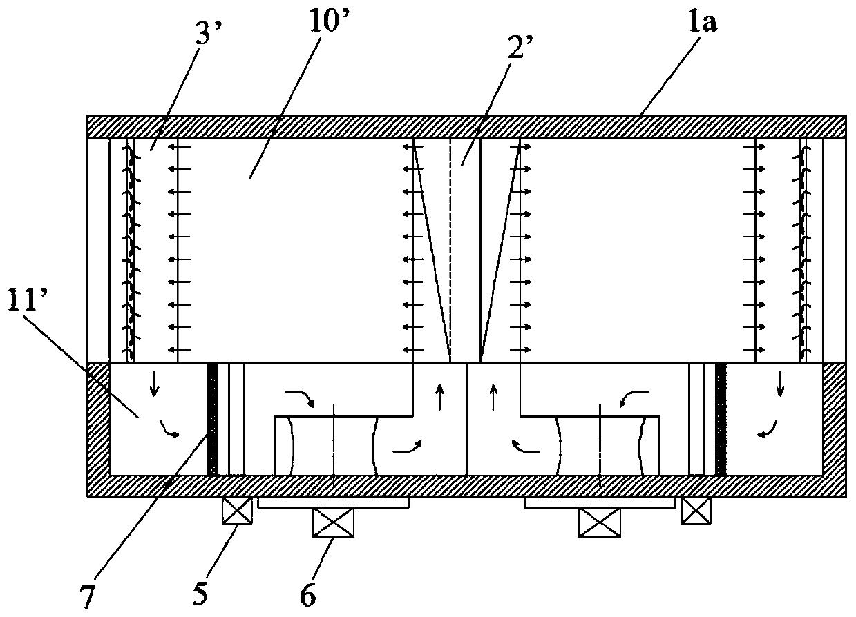
[0061] The long-term movement of the pre-oxidation furnace will easily block the first mesh plate 3 and the second mesh plate 4; so it is necessary to clean the first mesh plate and the second mesh plate online, specifically, as Figure 10 and 11 As shown, the furnace body of the present embodiment has a draw-in p...


PUM


Abstract

The invention belongs to the technical field of oxidation furnaces, and particularly relates to an air return box for a pre-oxidation furnace and the pre-oxidation furnace. The air return box for thepre-oxidation furnace comprises a first box body and a second box body which are sequentially arranged in the air return direction of the pre-oxidation furnace, and the first box body and the second box body are distributed at a preset interval. The side, facing the air return direction, of the first box body is provided with a first air return port; the second box body comprises an air return cavity body and a fresh air cavity which are sequentially distributed in the air return direction of the pre-oxidation furnace; the side, facing the air return direction, of the air return cavity body isprovided with a second air return port, and the fresh air cavity body is provided with a fresh air port for introducing fresh air. According to the air return box for the pre-oxidation furnace, two-stage air return is achieved in the air return direction, air return is sufficient, and hot air flow in the pre-oxidation furnace is not influenced.

Description

technical field [0001] The invention belongs to the technical field of oxidation furnaces, and in particular relates to a return air box for a pre-oxidation furnace and a pre-oxidation furnace. Background technique [0002] In the process of carbon fiber production, the pre-oxidation of the precursor plays a role of connecting the past and the future, and the pre-oxidation process of the precursor directly affects the yield and performance of carbon fiber. The purpose of the pre-oxidation process is to convert the thermoplastic PAN linear macromolecular chain into a non-plastic heat-resistant trapezoidal structure, making it infusible and non-combustible at high carbonization temperatures, maintaining the fiber shape, and thermodynamically in a stable state, and finally transforming into a turbostratic graphite structure. carbon fiber. According to the requirements of the pre-oxidation process, the pre-oxidation furnace came into being. [0003] Existing pre-oxidation furn...

Claims


Application Information

Patent Timeline
Patent Type & Authority Applications(China)
IPC IPC(8): D01F9/32
CPCD01F9/328
Inventor 张瑜傅建根金振峰王永法卫国军吴钟翔陈建林
Owner ZHEJIANG JINGGONG SCI & TECH
Why Eureka
Try Eureka