A stepped combustion chamber and inner wall of a nozzleless engine

A combustion chamber and engine technology, which is applied in the direction of machines/engines, rocket engine devices, mechanical equipment, etc., can solve the problems of weakened gas acceleration effect, small specific impulse, and small pressure gradient, so as to improve the gas acceleration effect and increase the ratio Impulse performance, improve the effect of specific impulse

A combustion chamber and engine technology, which is applied in the direction of machines/engines, rocket engine devices, mechanical equipment, etc., can solve the problems of weakened gas acceleration effect, small specific impulse, and small pressure gradient, so as to improve the gas acceleration effect and increase the ratio Impulse performance, improve the effect of specific impulse

CN110617160BActive Publication Date: 2022-06-28NANJING UNIV OF SCI & TECH

Image

  • A stepped combustion chamber and inner wall of a nozzleless engine
  • A stepped combustion chamber and inner wall of a nozzleless engine

Examples


Embodiment 1

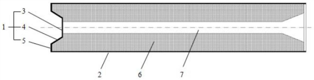
[0021] combine figure 1 , a stepped combustion inner wall of a nozzleless engine, comprising a radial wall surface 1 and an axial wall surface 2 of the head;

[0022] The radial wall surface 1 of the head is composed of an initial stepped wall surface 3, a transition wall surface 4 and a pressure-stabilizing stepped wall surface 5. The initial stepped wall surface 3 and the pressure-stabilizing stepped wall surface 5 are the same plane and are perpendicular to the engine axis; the transition The wall surface 4 has a certain gradient, and connects the initial step wall surface 3 and the stabilized step wall surface 5 as a whole.

[0023] The axial wall surface 2 is closely combined with the radial wall surface 1 of the head, and together constitute the inner wall of the combustion chamber.

[0024] The axial distance between the initial stepped wall surface 3 and the engine tail is relatively short, and the axial distance between the pressure-stabilizing stepped wall surface 5...


PUM


Abstract

The invention provides a stepped combustion chamber and an inner wall of a nozzleless engine. The inner wall of the combustion chamber includes a radial wall surface and an axial wall surface of the head; , the initial step wall and the pressure-stabilizing step wall are the same plane and perpendicular to the engine axis, the transition wall has a certain slope, and the initial step wall and the stabilizing step wall are connected as a whole; the axial wall is connected with the outer edge of the initial step wall and along the The combustion chamber extends axially; the axial wall and the radial wall of the head jointly form the combustion chamber.

Description

technical field [0001] The invention relates to an engine combustion chamber technology, in particular to a stepped combustion chamber and an inner wall of a nozzleless engine. Background technique [0002] Nozzleless motors are often used as the initial booster stage of solid rocket ramjets and are a unique solid rocket motor. It completes the replacement of the mechanical nozzle in the traditional thruster by using the gas choking effect, and has the advantages of simple structure, high reliability and relatively low cost. [0003] In order to ensure the necessary conditions for maintaining the gas choking effect during the working process of the engine, the length-diameter ratio of the nozzleless engine design must be large. Therefore, the unevenness of the combustion surface during its working process is very significant. In addition, because the gas passage changes with the working process due to the moving of the combustion surface, the change of the internal flow fie...

Claims


Application Information

Patent Timeline
28 Jun 2022
Publication
CN110617160B
IPC
F02K9/34
CPC
F02K9/34
Inventors
张小兵; 郑洪峰