Household garbage incineration treatment equipment

A technology of domestic waste incineration and treatment equipment

Active Publication Date: 2021-10-01
甘肃振毓新能源科技发展有限公司
View PDF12 Cites 2 Cited by
  • Summary
  • Abstract
  • Description
  • Claims
  • Application Information

AI Technical Summary

Problems solved by technology

[0005] One: In the process of incineration, it only relies on the combustibles in the domestic waste for combustion, which will lead to low incineration efficiency and incomplete incineration, and there is no simultaneous mixing of appropriate amount of coal powder in the process of waste incineration;
[0006] Its two: the fire grate in its incineration hearth is generally flat and fixed, causing the area of ​​incineration to be small and the ash after incineration, etc. cannot be discharged smoothly in time;
[0007] Third: the ash after incineration is easy to agglomerate, resulting in poor discharge of ash, and the ash after incineration can generally be reused, and the agglomerated ash makes secondary use inconvenient;
[0008] Fourth: During the process of garbage incineration, domestic garbage is directly transported to the incineration furnace, and there is no drying operation for the garbage before incineration, which makes incineration inconvenient;
[0009] Fifth: In the process of incineration, the fresh air from the outside is generally delivered to the incineration furnace by a blower. The oxygen in the fresh air plays a combustion-supporting function, and the temperature of the fresh air is low. When the fresh air with a low temperature is input into the furnace, it will Insufficient combustion of waste;
[0010] Sixth: The waste heat in the waste incineration process cannot be reliably utilized

Method used


Image

  • Household garbage incineration treatment equipment
  • Household garbage incineration treatment equipment
  • Household garbage incineration treatment equipment

Examples


Embodiment 1

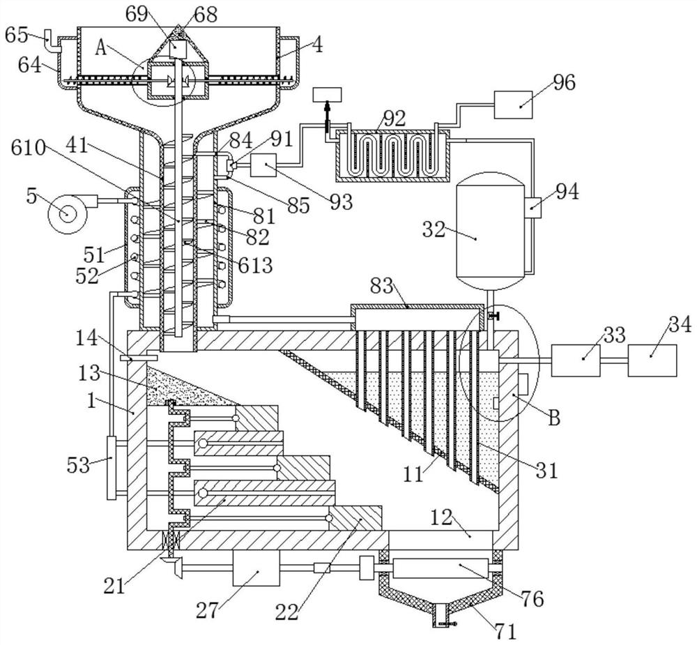
[0058] A domestic waste incineration treatment equipment, including a furnace 1, a fire grate, a power generation device, a hopper 4 and a blower 5;

[0059] Furnace 1 is a cuboid cavity structure, and the upper right corner of furnace 1 is fixed with a partition 11, which divides the inner cavity of furnace 1 into a combustion chamber and a steam chamber, and a slag port 12 is provided on the right side of the bottom plate of furnace 1;

[0060] The upper part of the inner wall of the left side plate of the furnace 1 is fixedly connected with a material guide seat 13, and the upper surface of the material guide seat 13 is arranged obliquely. below seat 13;

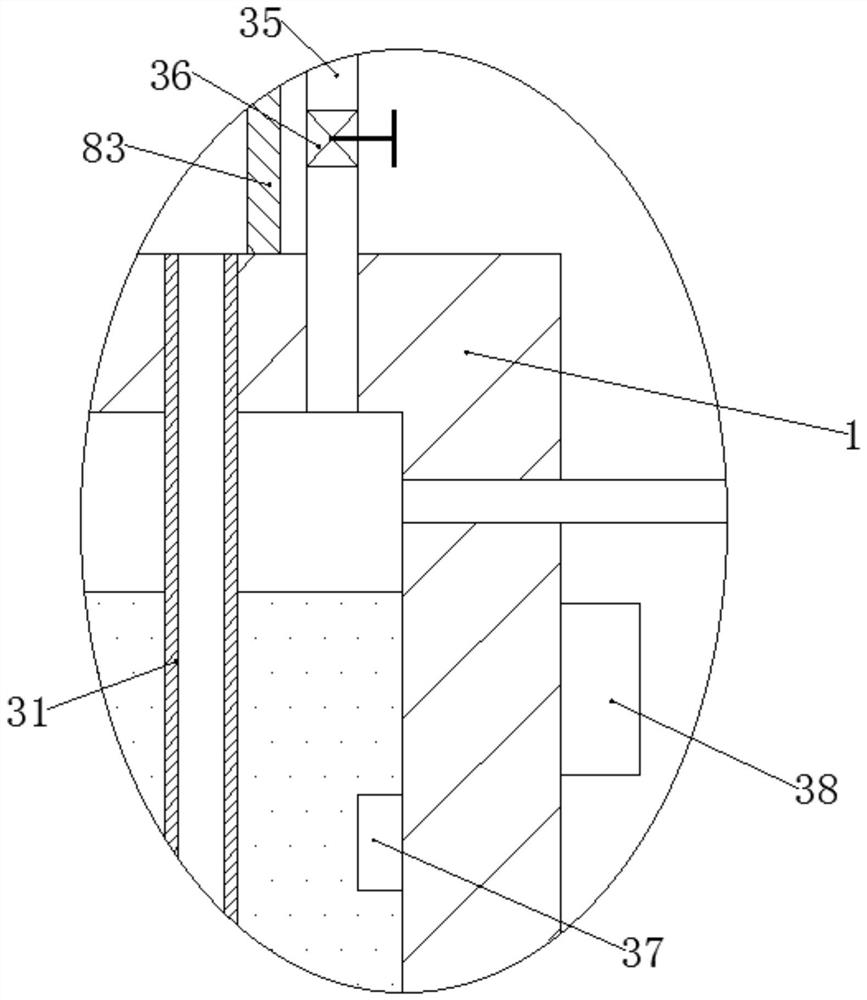
[0061] The power generation device includes an aluminum smoke pipe 31, a water tower 32, a steam turbine 33 and a generator 34; the top of the aluminum smoke pipe 31 is fixedly connected to the top plate of the furnace 1, and a plurality of aluminum smoke pipes 31 are uniformly arranged horizontally, and each aluminum smo...

Embodiment 2

[0069] The difference from Example 1 is that it also includes the following:

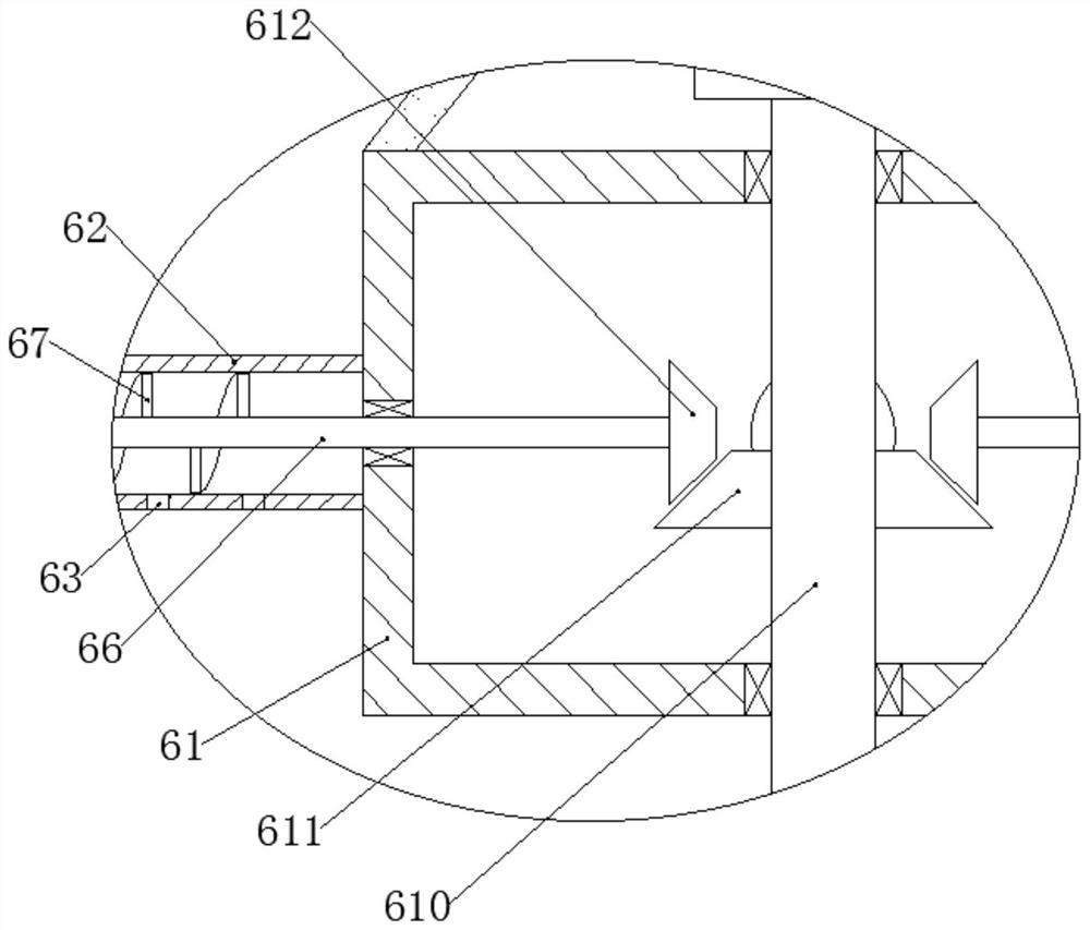
[0070] The center of the hopper 4 is provided with a transmission bin 61, the outer wall of the arc-shaped side plate of the transmission bin 61 is evenly fixed with a delivery pipe 62, the head of the delivery pipe 62 is fixedly connected with the side plate of the hopper 4, and the bottom of the delivery pipe 62 is densely covered with The discharge port 63 is fixedly connected with the outer wall of the side plate of the hopper 4 with an annular silo 64, the silo 64 covers the conveying pipes 62 in it, and the upper part of the silo 64 is fixedly connected with an adding pipe 65, which also includes a conveying shaft 66, the conveying shaft 66 is set coaxially with the conveying pipe 62 and is connected with the arc-shaped side plate of the transmission bin 61. One end of the conveying shaft 66 extends into the material bin 64, and the other end of the conveying shaft 66 extends into the transmiss...

Embodiment 3

[0075] The difference from Example 2 is that it also includes the following:

[0076] The fire grate includes a fixed fire grate 21 and a movable fire grate 22. The fixed fire grate 21 is fixedly connected between the front and rear side plates of the furnace 1 and arranged at vertical intervals. A moving grate 22 is slidably connected between adjacent fixed grates 21 and between the bottommost fixed grate 21 and the bottom plate of the furnace 1, and a shaft is rotatably connected between the bottom of the material guide seat 13 and the bottom plate of the furnace 1. Rod 23, the position corresponding to each movable fire grate 22 on the shaft rod 23 is all provided with U-shaped crankshaft 24, is hinged with connecting rod 25 between crankshaft 24 and corresponding mobile fire grate 22, and the bottom of shaft rod 23 is fixedly connected with the first Two driven bevel gears 26, the lower surface of the bottom plate of the furnace 1 is fixedly connected with a double-headed ...


PUM


Abstract

The invention discloses household garbage incineration treatment equipment which comprises a hearth, fire grates, a power generation device, a hopper and an air blower. The fire grates comprise the fixed fire grate and the movable fire grate, the power generation device comprises an aluminum smoke pipe, a water tower, a steam turbine and a power generator, a material pipe is fixedly connected to the bottom of the hopper, a heat exchange bin is fixedly connected to the material pipe, a cover bin is fixedly connected to the outside of the heat exchange bin, and a heat exchange pipe is fixedly connected into the cover bin. The equipment further comprises a waste heat recycling bin. Household garbage is conveyed to the fire grates in the hearth through a hopper and a material pipe to be combusted, steam is generated by energy generated during combustion, then power is generated through the power generation device, and external fresh air is conveyed into the hearth through the air blower to support combustion; and by adding pulverized coal, garbage combustion is more sufficient, garbage can be dried and fresh air can be preheated through the heat exchange bin, ash residues obtained after combustion can be smashed through a smashing roller, and waste heat can be further recycled through the waste heat recycling bin.

Description

technical field [0001] The invention relates to the technical field of garbage treatment, in particular to domestic garbage incineration treatment equipment. Background technique [0002] Household garbage refers to the solid waste generated by people in their daily life or in the activities that provide services for daily life. The garbage and waste produced also increased rapidly, and domestic garbage occupied land, polluted the environment, and affected people's health. The large increase in urban domestic garbage made garbage disposal more and more difficult. Environmental pollution and other issues have gradually aroused widespread concern from all walks of life. [0003] Power generation by incinerating domestic waste is one of the main means of waste disposal. It can not only process waste, but also generate electricity for people to use. [0004] But the existing waste incineration treatment equipment also has the following problems: [0005] One: In the process o...

Claims


Application Information

Patent Timeline
Patent Type & Authority Applications(China)
IPC IPC(8): F23G7/00F23G5/04F23G5/08F23G5/44F23G5/46F23J1/06
CPCF23G7/00F23G5/04F23G5/08F23G5/44F23G5/46F23J1/06Y02E20/12
Inventor 陈厚志
Owner 甘肃振毓新能源科技发展有限公司
Why Eureka
Try Eureka