Lam pholder with automatic clamping function based on gear drive principle

A gear transmission, principle technology, applied in discharge lamps, incandescent lamps, incandescent lamp parts and other directions, can solve the problems of long installation time, affecting the lighting effect of the lamp head, long connection time, etc., to ensure the installation speed and installation efficiency, The effect of preventing poor contact of the lamp head and reducing the trouble of installation

CN110645551AInactive Publication Date: 2020-01-03浦江功琪机械有限责任公司
8 Cites 6 Cited by

Patent Information

Authority / Receiving Office
CN · China
Patent Type
Applications(China)
Current Assignee / Owner
Publication Date
2020-01-03
Estimated Expiration
Not applicable · inactive patent

Smart Images

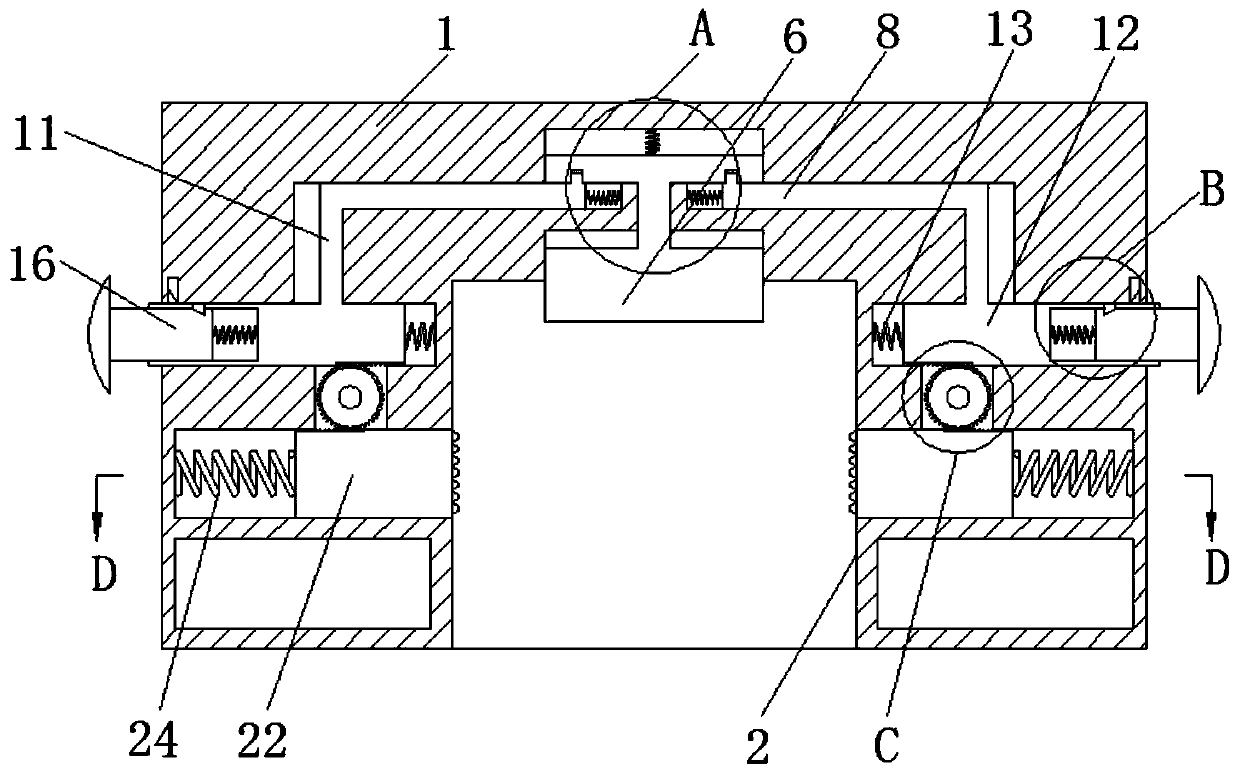
  • Figure 1
    Figure 1
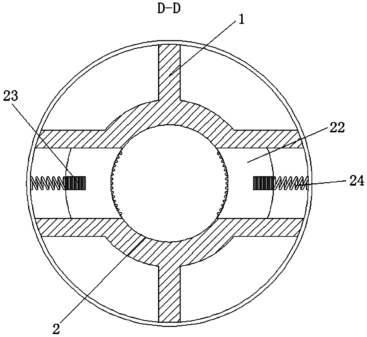
  • Figure 2
    Figure 2
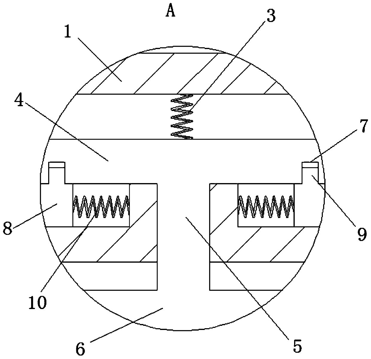
  • Figure 3
    Figure 3
Patent Text Reader

Abstract

The invention relates to the technical field of lamps, and discloses a lamp holder with an automatic clamping function based on the gear drive principle. The lamp holder comprises a housing, wherein alamp installation groove is formed in the housing, a first spring is fixedly connected to the interior of the housing, and a clamping plate is fixedly connected to the bottom of the first spring; a first connecting rod is fixedly connected to the bottom of the clamping plate, a jacking plate is fixedly connected to the bottom of the first connecting rod, clamping grooves are formed in the bottomof the clamping plate, clamping rods are movably connected to the bottom of the clamping plate, and clamping blocks are fixedly connected to the exteriors of the clamping rods. Through the cooperativeuse of the jacking plate and the clamping blocks, when a lamp cap jacks up the jacking plate, the clamping blocks automatically clamp the lamp cap under the actions of first push rods and fifth springs. Therefore, the lamp is convenient to install, the installation speed is high, the installation time is shortened for installation personnel, the situation that the installation personnel fall froma high place when installing the lamp for a long time is avoided, the efficiency of installing the lamp is improved, and the installation risk brought to the installation personnel is also reduced.
Need to check novelty before this filing date? Find Prior Art

Description

technical field

[0001] The invention relates to the technical field of lamps, in particular to an automatic clamping lamp holder based on the principle of gear transmission. Background technique

[0002] Edison, a great inventor, invented many things in his life. However, the only one that was warmly welcomed by people immediately was the electric light. Because the advantage of electric light is that people can see and touch it. Its appearance means that people have another round of the sun, and people's activities are no longer restricted by the night. Nowadays, the role of lighting fixtures is not only limited to lighting, but also the eyes of the home. More often, it plays a role of decoration. As a result, people's lives are becoming more and more inseparable from lighting.

[0003] Lighting lamps mainly include a lamp cap that provides a light source, a lamp holder for installing the lamp cap, a power supply and a switch for controlling the lamp. Nowadays, the techno...

Examples

Embodiment Construction

[0029] The following will clearly and completely describe the technical solutions in the embodiments of the present invention with reference to the accompanying drawings in the embodiments of the present invention. Obviously, the described embodiments are only some, not all, embodiments of the present invention. Based on the embodiments of the present invention, all other embodiments obtained by persons of ordinary skill in the art without making creative efforts belong to the protection scope of the present invention.

[0030] see Figure 1-8 , an automatic clamping lamp holder based on the principle of gear transmission, including a cover 1, a lamp installation groove 2, a first spring 3, a clamping plate 4, a first connecting rod 5, a top plate 6, a clamping groove 7, a clamping rod 8, Block 9, second spring 10, second connecting rod 11, first push rod 12, third spring 13, lock hole 14, fourth spring 15, second push rod 16, push groove 17, lock groove 18, lock Block 19, pu...