Wire drawing bushing for basalt fiber processing

A basalt fiber and wire drawing bushing technology, which is applied to manufacturing tools, glass manufacturing equipment, etc., can solve the problems of insufficient heating of the melt, difficulty in clearing blockages, and inability to perform wire drawing bushing work, etc. cleaning effect

Active Publication Date: 2020-01-17
太原市鼎泰达建材有限公司
View PDF14 Cites 5 Cited by
  • Summary
  • Abstract
  • Description
  • Claims
  • Application Information

AI Technical Summary

Problems solved by technology

[0004] However, the existing wire drawing bushing heats the basalt melt through the bottom plate 2, the heat of the upper and lower layers of the melt located in the bushing shell 1 is uneven, and the melt flows quickly through the drain nozzle 201 under the force of gravity, resulting in uneven heating of the melt. Sufficient, affecting the effect of wire drawing, when the depth of the nozzle 201 is increased to ensure that the melt is sufficiently heated for wire drawing, because the existing wire drawing bushing is equipped with a cooling mechanism at the bottom of the bottom plate 2, so that the wire drawing melt Rapid cooling and molding, at this time, the depth of the leak nozzle 201 is relatively long, and the heat exchange caused by the operation has a great influence, and the temperature of the solution flowing through the bottom plate cannot be guaranteed to be uniform, which affects the solution outflow effect, resulting in crystallization and leak nozzle blockage. And it is difficult to clean the blockage located in the leak nozzle, which leads to the inability to carry out the work of the drawing bushing

Method used


Image

  • Wire drawing bushing for basalt fiber processing
  • Wire drawing bushing for basalt fiber processing
  • Wire drawing bushing for basalt fiber processing

Examples


Embodiment Construction

[0016] The following will clearly and completely describe the technical solutions in the embodiments of the present invention with reference to the accompanying drawings in the embodiments of the present invention. Obviously, the described embodiments are only some, not all, embodiments of the present invention. Based on the embodiments of the present invention, all other embodiments obtained by persons of ordinary skill in the art without making creative efforts belong to the protection scope of the present invention.

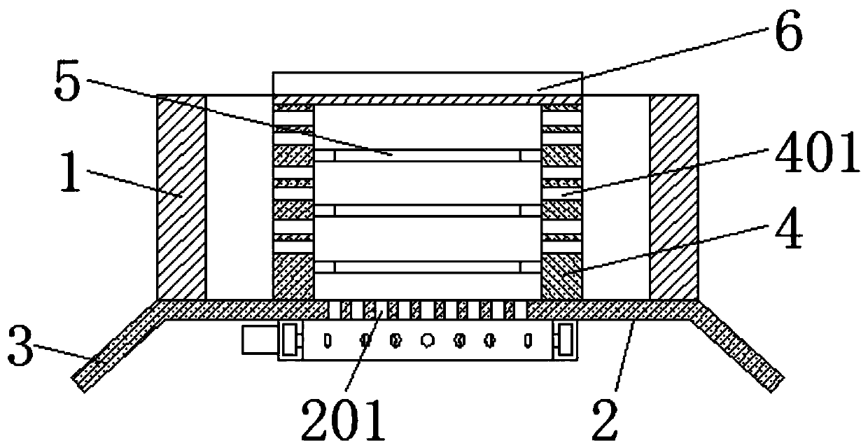
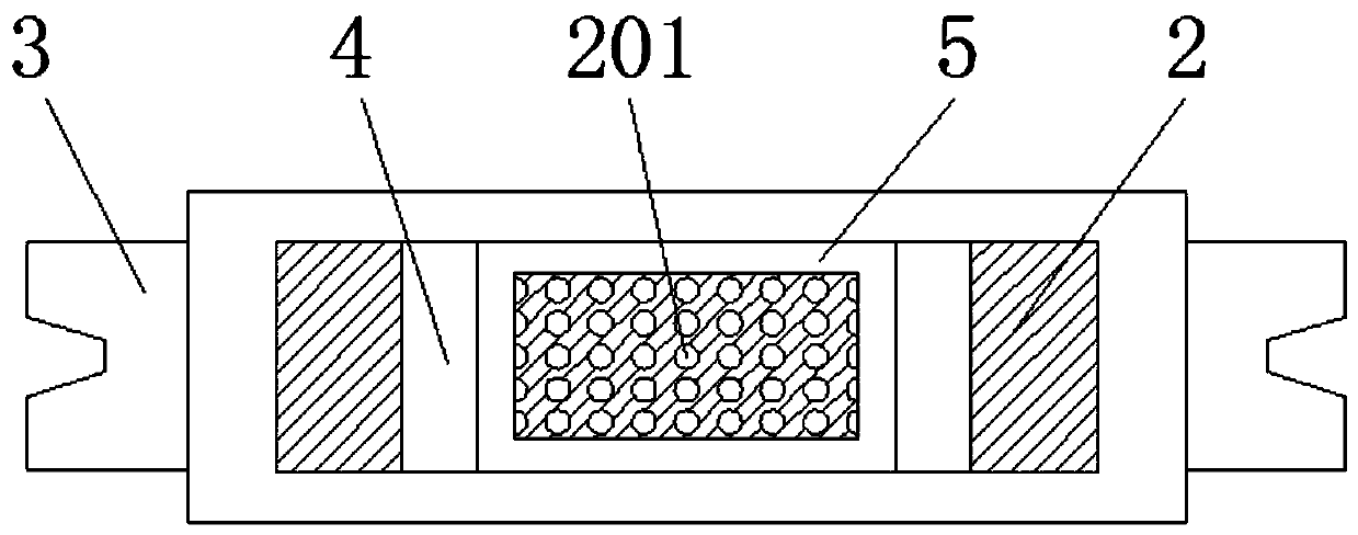
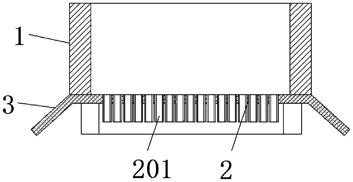
[0017] see Figure 1-2 , a wire drawing bushing for basalt fiber processing, comprising a bushing shell 1, a bottom plate 2, a leak nozzle 201, an electrode 3, and reinforcing ribs 5, the bottom plate 2 is fixedly installed on the bottom of the bushing shell 1, and the bottom plate 2 is provided with There are a number of leak nozzles 201 arranged equidistantly. Two opposite electrodes 3 are electrically connected to both sides of the bottom plate 2. The two e...


PUM


Abstract

The invention relates to the field of basalt fiber processing equipment, and discloses a wire drawing bushing plate for basalt fiber processing. The wire drawing bushing plate for basalt fiber processing comprises a bushing plate shell, a bottom plate, discharge spouts, electrodes, preheating plates and reinforcing ribs; the bottom plate is arranged at the bottom of the bushing plate shell, two opposite electrodes are electrically connected to the two sides of the bottom plate, and the discharge spouts arranged at equal intervals are formed in the bottom of the bottom plate; two preheating plates are arranged in a bushing plate shell; flowing molten liquid is heated by the preheating plates, so that the to-be-drawn molten liquid is uniformly and sufficiently heated; the depth of the bottomplate discharge spouts is also reduced, so that wire drawing work can be carried out conveniently, and it is effectively guaranteed that the to-be-drawn molten liquid located above the bottom plate is sufficiently and evenly heated; the depth of the discharge spouts is small, so that the influence on heat exchange is small, the problem that the discharge spouts are blocked because of crystallization when the temperature of the molten liquid is not high enough is solved without influencing molten liquid flowing out effect, and blocking substances at openings of the discharge spouts are easy toclean.

Description

technical field [0001] The invention relates to the field of basalt fiber processing equipment, in particular to a drawing bushing used for basalt fiber processing. Background technique [0002] Basalt is an electrodeless silicate that has been tempered over fire and in a furnace to change from hard rock to soft fiber. Compared with glass fiber, its material has thermal conductivity, low hygroscopicity, corrosion resistance, Excellent properties such as radiation resistance and high crack resistance and excellent processing performance are widely used to make high-end products. In the process of basalt fiber processing, the drawing bushing is an indispensable fiber drawing equipment. [0003] The working principle of the existing fiber drawing bushing is as follows (refer to image 3 ): The basalt melt enters the cavity inside the drain plate shell 1, and energizes the two electrodes 3 on both sides of the bottom plate 2, so that the bottom plate 2 heats the upper melt, and ...

Claims


Application Information

Patent Timeline
Patent Type & Authority Applications(China)
IPC IPC(8): C03B37/08C03C13/06
CPCC03B37/08C03C13/06
Inventor 丁胜利
Owner 太原市鼎泰达建材有限公司
Why Eureka
Try Eureka