
Inverter controlling method and device
A control method and a technology of a control device, which are applied to circuit devices, output power conversion devices, AC power input conversion to DC power output, etc., can solve problems affecting the safe operation of inverters, etc.
- Summary
- Abstract
- Description
- Claims
- Application Information
AI Technical Summary
Problems solved by technology
Method used
Image

Examples
Embodiment Construction
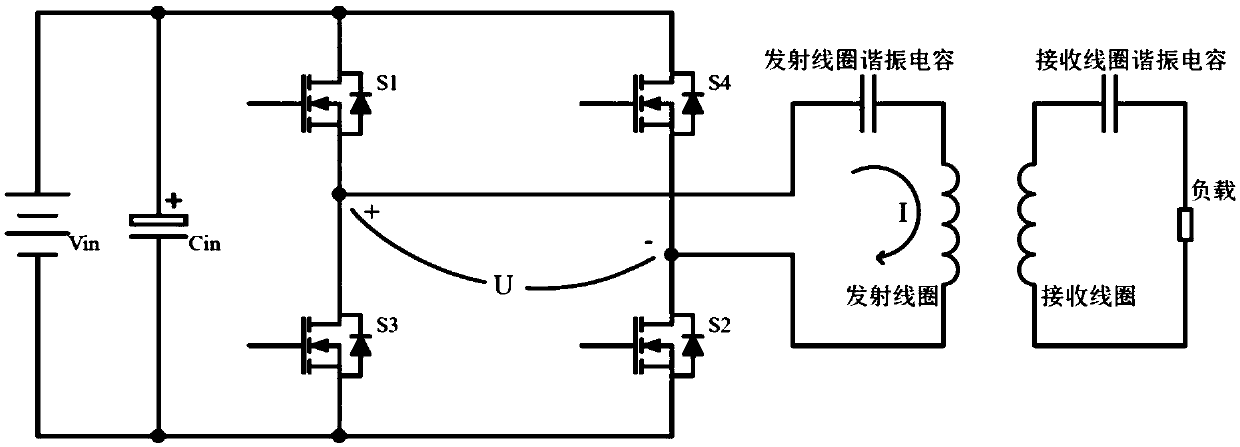
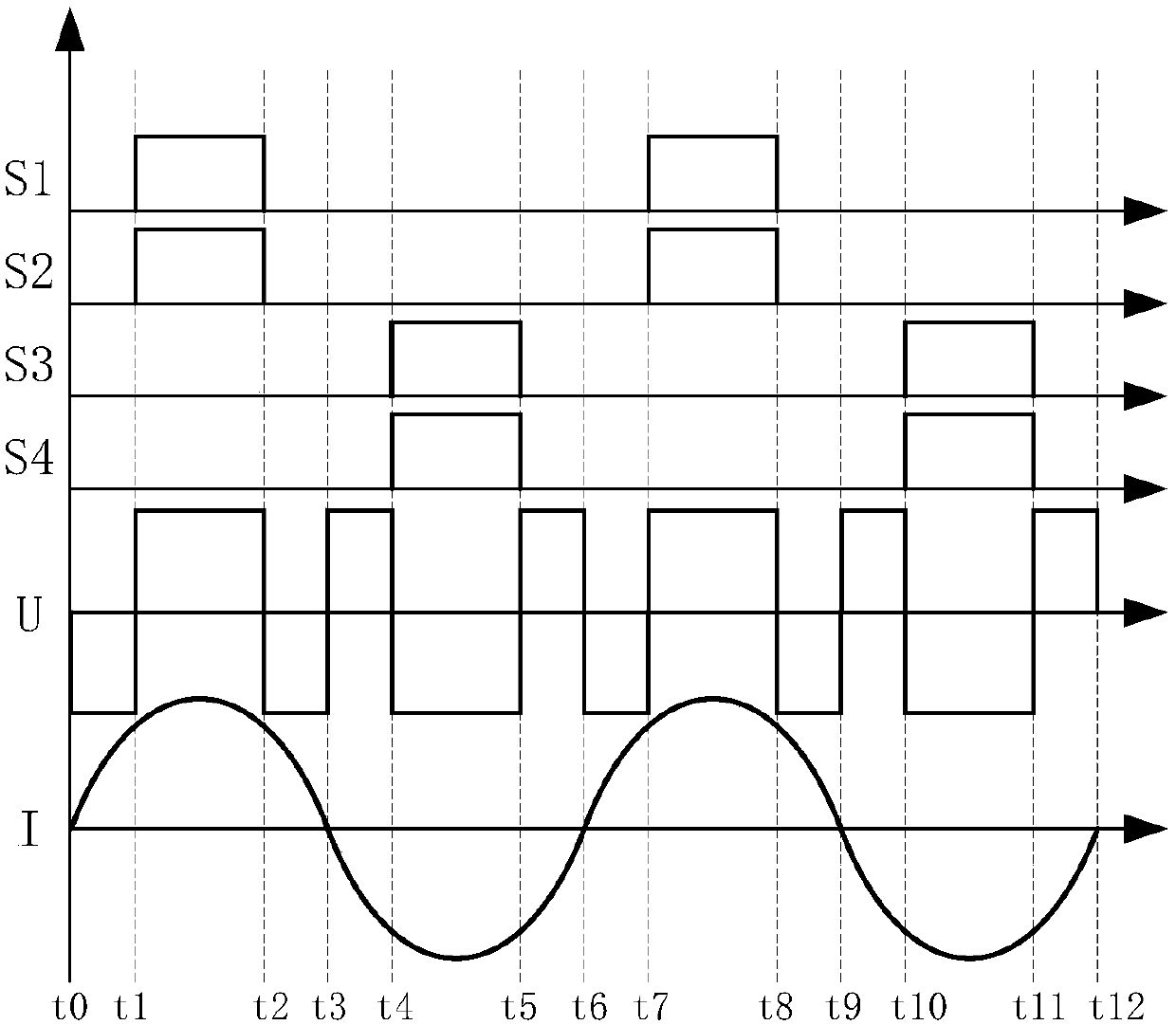
[0028] The object of the present invention is to provide an inverter control method and device for solving the problem in the prior art that the safe operation of the inverter is affected due to the phenomenon of hard switching when controlling the full-bridge inverter.
[0029] To achieve the above object, the technical solution provided by the invention is:
[0030] A method for controlling an inverter, comprising the steps of:
[0031] Control each switching tube of the inverter according to the control sequence of the control cycle;
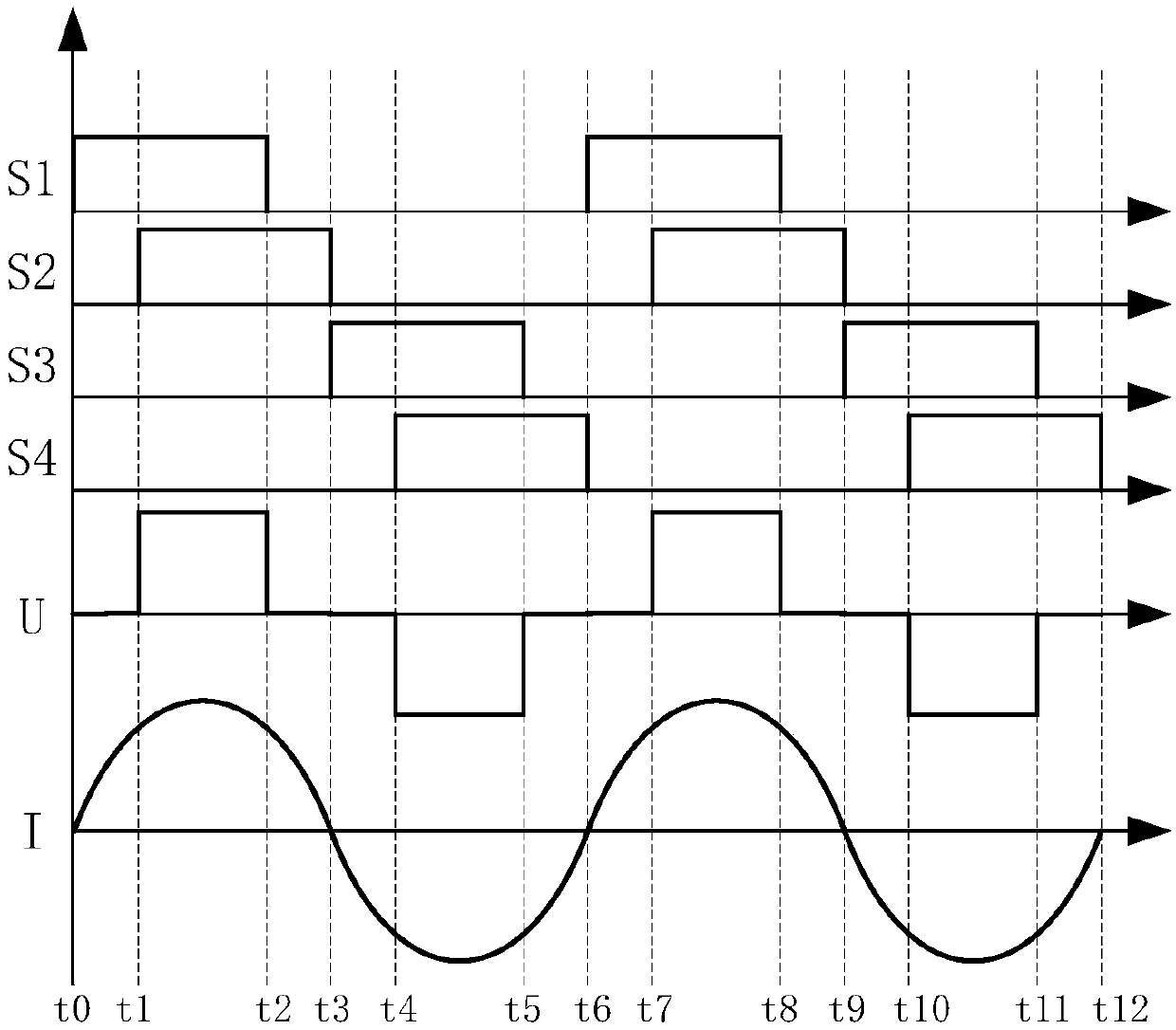
[0032] Assume that one of the bridge arms of the inverter is the leading arm, and the other bridge arm is the lagging arm; at the beginning of a control cycle, the first switching tube of the leading arm is first controlled to be turned on, and the first switching tube of the leading arm is turned on After the first set time, the second switching tube of the lagging arm is controlled to be turned on; when the second switching tube of the lag...
PUM
 Abstract
Description
Claims
Application Information