
Energy network security management optimization method based on large-scale new energy grid connection

A technology of network security and optimization method, which is applied in the field of collaborative optimization and scheduling of multi-energy systems to achieve the effect of improving the utilization rate of new energy power generation, improving the safety level of energy supply, and maintaining the security and stability of the system.

Pending Publication Date: 2022-05-27
QINGHAI ELECTRIC POWER DESIGN INST
View PDF0 Cites 0 Cited by
  • Summary
  • Abstract
  • Description
  • Claims
  • Application Information

AI Technical Summary

Problems solved by technology

On the other hand, with the increase of the penetration rate of new energy, the randomness and fluctuation of its output pose great challenges to the normal operation of the power grid.

Method used


Image

  • Energy network security management optimization method based on large-scale new energy grid connection
  • Energy network security management optimization method based on large-scale new energy grid connection
  • Energy network security management optimization method based on large-scale new energy grid connection

Examples


Embodiment 1

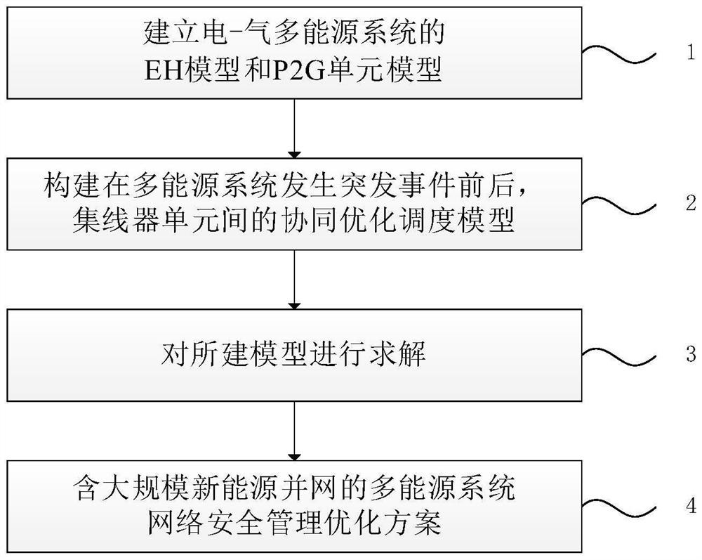
[0092] like figure 1 As shown, this embodiment provides an energy network security management optimization method based on large-scale new energy grid connection, including the following steps:

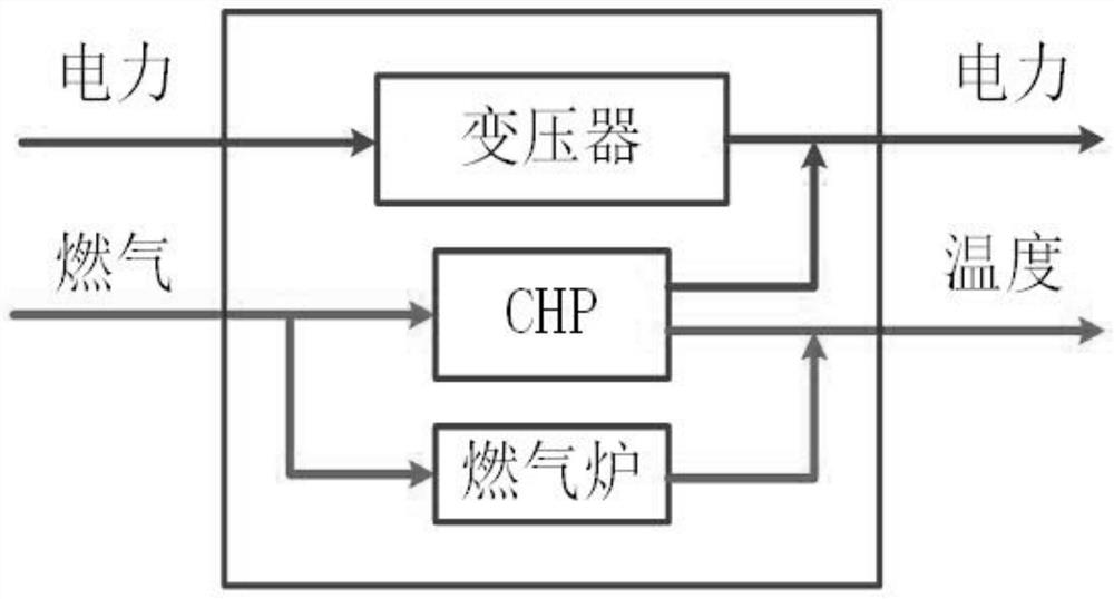
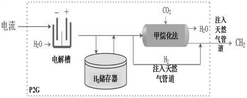
[0093] Step S1: establish the EH model and the P2G unit model of the multi-energy system;

[0094] Step S2: constructing a coordinated optimal scheduling model between multi-energy hub units including large-scale new energy grid-connected before and after an emergency occurs in the system power grid or natural gas network;

[0095] Step S3: solve the built model;

[0096] Step S4: Obtain an optimal scheme for collaborative optimization scheduling among multi-energy hub units including large-scale new energy grid-connected units.

[0097] The optimal scheduling model proposed by the present invention contains a large number of equality and inequality constraints, and its solution has certain complexity. The GAMS language has strong flexibility and versatility, and has high solving e...

Embodiment 2

[0162] like Figure 4 As shown, a network composed of 14 energy hub units is taken as the research object, in which energy exchange can be performed between each hub unit. Among them, the first, second and sixth energy hubs are energy centers in industrial areas, and the remaining units are energy centers in residential areas. The entire network includes two power grids and two gas grids, hubs 1 to 6 are powered by the first grid and the first gas grid, and hubs 7 to 14 are powered by the second grid and the second gas grid. P2G units supply gas to two gas networks respectively. Power can be exchanged between 1-6 hub units, and power can be exchanged between 7-14 hubs. 1, 5, and 6 hubs can only exchange thermal energy between each other, and all other hubs can exchange thermal energy. The optimal scheduling step is one hour.

[0163] Four different electricity and gas emergency scenarios are considered. The first and second scenarios are contingencies of the first and sec...


PUM


Abstract

The invention belongs to the field of multi-energy system collaborative optimization scheduling, and particularly relates to an energy network security management optimization method based on large-scale new energy grid connection, which comprises the following steps: establishing an EH model and a P2G unit model of a multi-energy system; constructing a collaborative optimization scheduling model between multi-energy concentrator units containing large-scale new energy grid connection before and after an emergency occurs in a system power grid or a natural gas network; and solving the established model to obtain a collaborative optimization scheduling optimal scheme among the multi-energy concentrator units containing large-scale new energy grid connection. According to the energy network security management optimization method based on large-scale new energy grid connection, the energy supply security of the system can be remarkably improved, and the absorption problem of new energy power generation can be effectively solved.

Description

technical field [0001] The invention belongs to the field of collaborative optimization and scheduling of multi-energy systems, and in particular relates to an energy network security management optimization method based on large-scale new energy grid connection. Background technique [0002] In recent years, the advantages of multi-energy systems in optimizing energy structure and improving energy utilization efficiency have become increasingly prominent, so they have received extensive attention. The energy hub is the interface platform between the source, the network and the load in the multi-energy system. With the increase of the number of EHs, it is necessary to optimize the management of the energy network from the perspective of energy security of the entire system. On the other hand, with the increase of the penetration rate of new energy, the randomness and volatility of its output pose a great challenge to the normal operation of the power grid. Therefore, it is ...

Claims


Application Information

Patent Timeline
IPC IPC(8): H02J3/38H02J3/28
CPCH02J3/381H02J3/28H02J2203/20H02J2300/24H02J2300/28Y04S10/50
Inventor 韩明亮李美玲杨丽张玮赵俊杰陈静怡陈永琦马昕熠张文松王正辉张丽娟岳超李兴李鑫李洛张舒凯李积鹏
Owner QINGHAI ELECTRIC POWER DESIGN INST
Learn More