Flame hole unit structure of combustion apparatus
A combustion device and flame hole technology, applied in the direction of burner safety device, burner, burner, etc., can solve the problems of easy extinguishment, unstable flame, etc., and achieve the effect of reducing NOx and uniform flame stability
- Summary
- Abstract
- Description
- Claims
- Application Information
AI Technical Summary
Problems solved by technology
Method used
Image
Examples
Embodiment approach 1
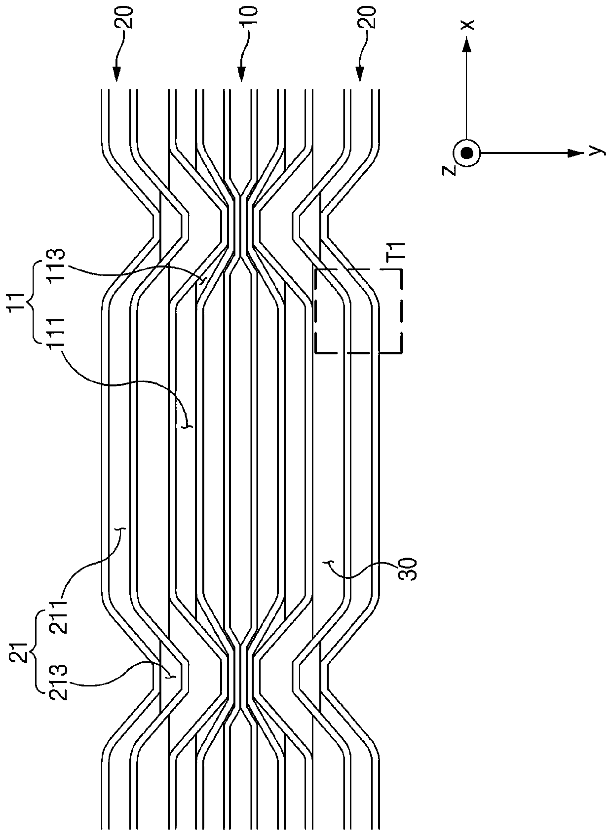
[0037] image 3 is a plan view showing the flame hole structure according to Embodiment 1 of the present invention. Figure 4 is showing image 3 A magnified view of region T1 in the fuel-rich flame hole. Figure 5 is a plan view showing the flame hole structure according to Embodiment 1 of the present invention in another aspect. Image 6 is showing Figure 5 An enlarged view of the region T2. In the following, reference will be made to Figure 3 to Figure 6 A flame hole structure of a combustion device including a plurality of flame holes for forming a flame according to Embodiment 1 of the present invention will be described.
[0038] The flame hole structure according to Embodiment 1 of the present invention includes a lean flame hole part 10 and a rich flame hole part 20 .
[0039] The lean flame hole component 10 includes at least one lean flame hole 11 for releasing lean gas. The lean flame hole 11 extends along a length direction x which is a direction perpendic...
Embodiment approach 2
[0075] Figure 7 is a plan view showing a flame hole structure according to Embodiment 2 of the present invention. Figure 8 is showing Figure 7 A magnified view of the region T3. In the following, reference will be made to Figure 7 and Figure 8 A flame hole structure according to Embodiment 2 of the present invention will be described. In the flame hole structure according to Embodiment 2, the same components as Embodiment 1 will be described using the same reference numerals.
[0076] Like the flame hole structure according to Embodiment 1, the flame hole structure according to Embodiment 2 of the present invention includes a lean flame hole part 10 and a rich flame hole part 20 . The lean flame hole part 10 includes a lean flame hole 11 formed by a plurality of lean plates 13 and a rich flame hole 21 formed by a first rich plate 23a and a second rich plate 23b.
[0077] In addition, the plurality of lean plates 13 include a curved lean plate portion 133 and a horiz...
Embodiment approach 3
[0082] Figure 9 is a plan view showing a flame hole structure according to Embodiment 3 of the present invention. Figure 10 is a plan view showing a flame hole structure according to Embodiment 3 of the present invention. Figure 11 is shown along Figure 9 Schematic diagram of the cross-section taken by line C-C in . In the following, reference will be made to Figure 9 to Figure 11 A flame hole structure according to Embodiment 3 of the present invention will be described. In the flame hole structure according to Embodiment 3, the same components as Embodiments 1 and 2 will be described using the same reference numerals, and unnecessary description will be omitted.
[0083] The flame hole structure according to Embodiment 3 of the present invention may further include the coupling member 40 in the flame hole structures according to Embodiments 1 and 2. Referring to FIG. The joining member 40 refers to a member passing through the rich flame hole part 20 and the lean fla...
PUM
 Abstract
Description
Claims
Application Information
 - R&D
- Intellectual Property
- Life Sciences
- Materials
- Tech Scout
- Unparalleled Data Quality
- Higher Quality Content
- 60% Fewer Hallucinations
Browse by: Latest US Patents, China's latest patents, Technical Efficacy Thesaurus, Application Domain, Technology Topic, Popular Technical Reports.
© 2025 PatSnap. All rights reserved.Legal|Privacy policy|Modern Slavery Act Transparency Statement|Sitemap|About US| Contact US: help@patsnap.com


