Ceramic closed cavity structure of high-voltage relay, high-voltage relay, and working method of high-voltage relay

A high-voltage relay and closed cavity technology, applied in relays, electromagnetic relays, detailed information of electromagnetic relays, etc., can solve problems such as unreliable contact and failure of relays, improve the ability to resist extreme high current shocks, and improve reverse voltage capabilities , to ensure the effect of contact reliability

Active Publication Date: 2020-05-12
SHANGHAI HUGONG AUTO ELECTRIC
View PDF4 Cites 3 Cited by
  • Summary
  • Abstract
  • Description
  • Claims
  • Application Information

AI Technical Summary

Problems solved by technology

[0005] One is: the directional problem of requiring external loads due to the addition of permanent magnets
[0006] The second is: due to the electromagnetic force generated by the super-large current in the magnetic field, the contact piece bounces off, resulting in unreliable contact or even failure of the relay.

Method used


Image

  • Ceramic closed cavity structure of high-voltage relay, high-voltage relay, and working method of high-voltage relay
  • Ceramic closed cavity structure of high-voltage relay, high-voltage relay, and working method of high-voltage relay
  • Ceramic closed cavity structure of high-voltage relay, high-voltage relay, and working method of high-voltage relay

Examples


Embodiment 1

[0047] Embodiment one (comparative example):

[0048] Examples of arc extinguishing work for existing relays:

[0049] For the convenience of introduction, the structure here is simplified, see Figure 3-6 : The permanent magnets of existing products are arranged on both sides of the contact point rod in the Y direction, such as Figure 3-4 Shown, the arc extinguishing magnetic field produced by the permanent magnet, continue to refer to Figure 5-6 , when the external high-voltage and high-current load of the relay presses Figure four When the forward flow occurs, the arc between the contact piece and the contact rod is pulled to both sides of the contact rod according to the left-hand rule under the action of the magnetic field formed by the permanent magnet, so as to thin the arc and quickly extinguish it. purpose, such as Figure 6 shown; otherwise, as Figure 7-8 As shown, if the external high-voltage and large current is reversed, that is, when it flows in reverse,...

Embodiment 2

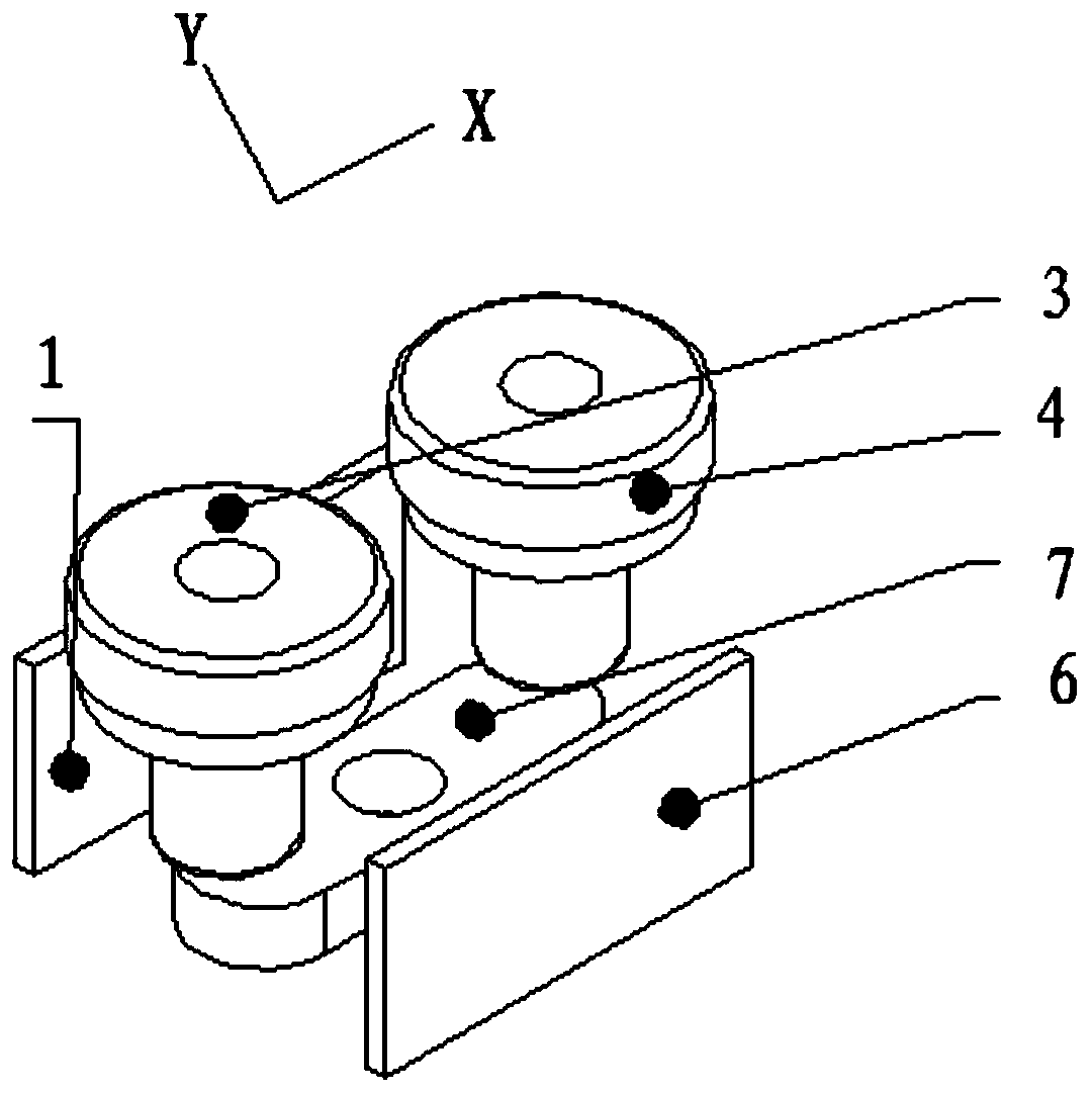
[0053] For the convenience of introduction, the structure here is simplified, see Figure 9-13 :

[0054] The relay sets its permanent magnets on the left and right sides of the contact rod in the X direction, such as Figure 10 As shown, the arc extinguishing magnetic field produced by the permanent magnet is as follows Figure 9 As shown, when the external high-voltage and high-current load of the relay is pressed Figure 12 In the forward direction, the arc between the contact piece and the contact rod is under the action of the magnetic field formed by the permanent magnet. According to the left-hand rule, the arc of the left contact rod 3 is pulled to the left, and the arc of the right contact rod 4 is pulled to the left. The arc is pulled to the right to achieve the purpose of thinning the arc and extinguishing it quickly, such as Figure 11-13 Conversely, if the external high-voltage and large current is reversed, the arc of the right contact rod 3 is pulled to the r...


PUM


Abstract

The invention relates to a ceramic closed cavity structure of a high-voltage relay. The direction of the axis connecting line of a pair of contact rods is the X direction, and the direction perpendicular to the axis connecting line of the pair of contact rods is the Y direction; a pair of oppositely-arranged permanent magnets are arranged at the positions, located on the two sides of the pair of contact rods, in the X direction; an upper magnetic conductive ring and a lower magnetic conductive ring are added at two ends of a contact piece for conducting the contact rod, and the upper magneticconductive ring is fixedly connected with the pull rod shaft; the top of the pull rod shaft is fixedly connected with the upper magnetic conductive ring, the lower magnetic conductive ring is providedwith a small hole allowing the pull rod shaft to freely penetrate through and supported by the overtravel spring; one end of the overtravel spring is fixed, and the other end of the overtravel springcan drive the lower magnetic conductive ring to float. When an extremely large current passes through the contact piece, the periphery of the contact piece generates a closed annular magnetic circuitalong the upper magnetic conductive ring and the lower magnetic conductive ring, and the lower magnetic conductive ring has upward thrust to the contact piece under the action of electromagnetic attraction, so downward separation force generated by the extremely large current to the contact piece is overcome and counteracted.

Description

technical field [0001] The invention relates to a high-voltage relay and belongs to the technical field of relays. Background technique [0002] The high-voltage relay is the connection channel between the new energy vehicle battery system and the motor controller, and is the necessary and core electronic control basic component in the medium and high voltage system of the new energy vehicle. Its function is to turn on or off the high-voltage and high-current load. Due to the small installation space on the car, the high-voltage relay for the car must have the basic functions of high voltage resistance, load resistance, impact resistance, arc extinguishing ability and breaking ability. In addition, it also needs to be small in size and compact in structure. Whether the above requirements can be realized depends on the structural design of the key component of the high voltage relay - the ceramic sealed cavity. [0003] In the process of connecting or disconnecting high-vol...

Claims


Application Information

Patent Timeline
Patent Type & Authority Applications(China)
IPC IPC(8): H01H50/02H01H50/56H01H50/64
CPCH01H50/023H01H50/56H01H50/641
Inventor 黄国忠席杰明王晓兰
Owner SHANGHAI HUGONG AUTO ELECTRIC
Why Eureka
Try Eureka