Optical cross connection equipment for metro backbone transport network

An optical cross-connection and transmission network technology, applied in optics, light guides, optical components, etc., can solve problems such as difficulty in straightening, weak management ability, and small equipment capacity, and achieve the effect of convenient direct connection of fiber cores

Active Publication Date: 2020-06-05
CHINA MOBILE GROUP DESIGN INST +1
View PDF7 Cites 0 Cited by
  • Summary
  • Abstract
  • Description
  • Claims
  • Application Information

AI Technical Summary

Problems solved by technology

[0004] But, above-mentioned prior art has following shortcoming: (1) equipment capacity is little: the capacity of common ODF standard rack is generally 576 cores; When connecting a fiber jumper, when the capacity of the ODF exceeds 2 / 3, too many fiber jumpers will appear messy and difficult to straighten out, making it difficult to manage the connection relationship of the fiber core; (3) Lack of effective management of the ODF port : The traditional ODF does not have the network management function, and the use of each port of the ODF can only be recorded manually, which is difficult to dynamically adjust according to the actual use; (4) The cross-connection capability is weak: when two different Neighboring nodes (such as figure 1 When there is an optical fiber direct connection service requirement between nodes A and P), it must pass through an intermediate node (such as figure 1 Node B or node O) ODF fiber jumper can be realized; if there is a 48-core direct connection service between A and P, 48 single-core jumper fibers must be connected through node B or node O
Due to the weak management ability of traditional ODF on ports and fiber jumpers, it is difficult to adapt to a large number of direct connections between fiber cores across nodes

Method used


Image

  • Optical cross connection equipment for metro backbone transport network
  • Optical cross connection equipment for metro backbone transport network
  • Optical cross connection equipment for metro backbone transport network

Examples


Embodiment Construction

[0031] The specific embodiments of the present invention will be further described below in conjunction with the accompanying drawings. The following examples are only used to illustrate the technical solution of the present invention more clearly, but not to limit the protection scope of the present invention.

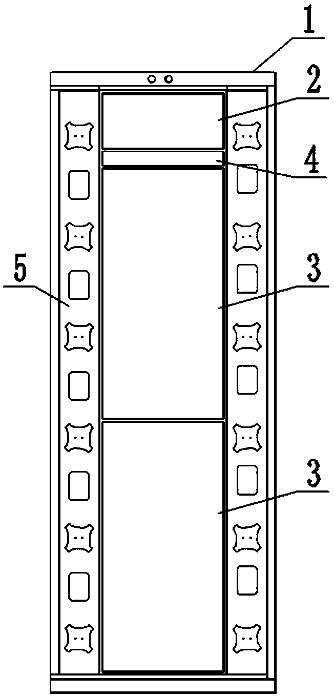
[0032] figure 2 A schematic structural diagram of a metro backbone transport network optical cross-connect device provided by an embodiment of the present invention is shown, as shown in figure 2 As shown, the optical cross-connect device of the metro backbone transport network in this embodiment includes: a frame body 1, an optical cable fixing device 2, a plurality of optical cross-connect subracks 3, a fiber core intelligent management unit 4 and a fiber jumper storage unit 5;

[0033] The frame body 1 provides an installation space for equipment, and each frame body 1 is equipped with an optical cable fixing device 2, a plurality of optical cross-connect subrac...


PUM


Abstract

The invention discloses optical cross connection equipment for a metro backbone transport network. The optical cross connection equipment comprises frame bodies, optical cable fixing devices, a plurality of optical cross connection sub-frames, an intelligent fiber core management unit and a jumper fiber storage unit, wherein the frame body provides an installation space for equipment, and each frame body is internally provided with an optical cable fixing device, a plurality of optical cross connection sub-frames, the intelligent fiber core management unit and the jumper fiber storage unit; the optical cable fixing device is used for fixing external optical cables; a multi-core movable connector assembly is arranged in the optical cross connection sub-frame, so that each optical fiber in the external optical cable is formed at a port of the multi-core movable connector assembly and has cross capability; the intelligent fiber core management unit is used for identifying the electronic tags at the two ends of the jumper fiber so as to realize intelligent management of the use condition of the fiber core; and the jumper fiber storage unit is used for storing the excess length of the jumper fiber. The problems that an existing ODF device is small in device capacity, the number of jumper fibers in the device is large, the cross connection capacity of the device is poor, and effective management of an ODF port is lacked can be solved.

Description

technical field [0001] The embodiment of the present invention relates to the fields of transmission and IP (interconnection protocol between networks), and specifically relates to an optical cross-connection device of a metro backbone transport network. Background technique [0002] In recent years, with the rapid development of data services, more and more services are directly connected between backbone nodes of the metro backbone transport network through optical fibers. [0003] figure 1 It is a network structure diagram of the core layer optical cable of a backbone transmission network. The number of cores of optical cables between backbone nodes in the metropolitan area is generally relatively large. In the prior art, optical cables are terminated on ODF (Optical Distribution Frame, Optical Distribution Frame) in the backbone nodes, and each optical fiber in the optical cable is terminated On a single-core FC / SC connector port of the ODF, services are connected from...

Claims


Application Information

Patent Timeline
IPC IPC(8): G02B6/38G02B6/40
CPCG02B6/3825G02B6/40
Inventor 丁为民孟庆松刘勇王勇陈一伟朱亮
Owner CHINA MOBILE GROUP DESIGN INST
Why Eureka
Try Eureka