
A medical reagent card automatic assembly machine
An automatic assembly machine and reagent card technology, which is applied in the field of medical reagent production, can solve the problems of loose material distribution, low efficiency, and difficulty in concentrating assembly stations, and achieve the effects of increasing assembly speed, simplifying assembly space, and improving accuracy
- Summary
- Abstract
- Description
- Claims
- Application Information
AI Technical Summary
Problems solved by technology
Method used
Image

Examples
Embodiment Construction
[0031] In order to enable those skilled in the art to better understand the technical solutions of the present invention, the present invention will be further described in detail below in conjunction with the accompanying drawings.
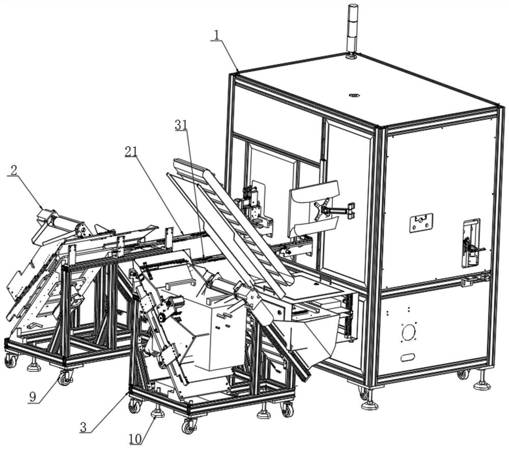
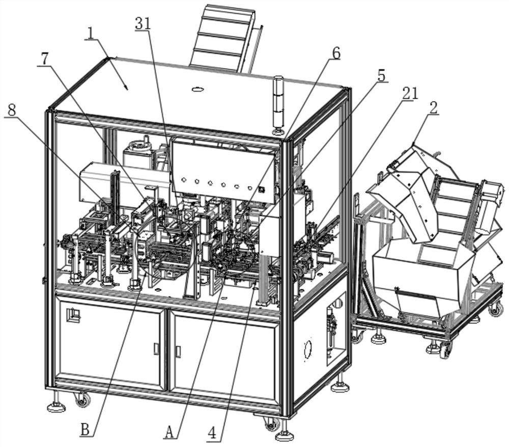
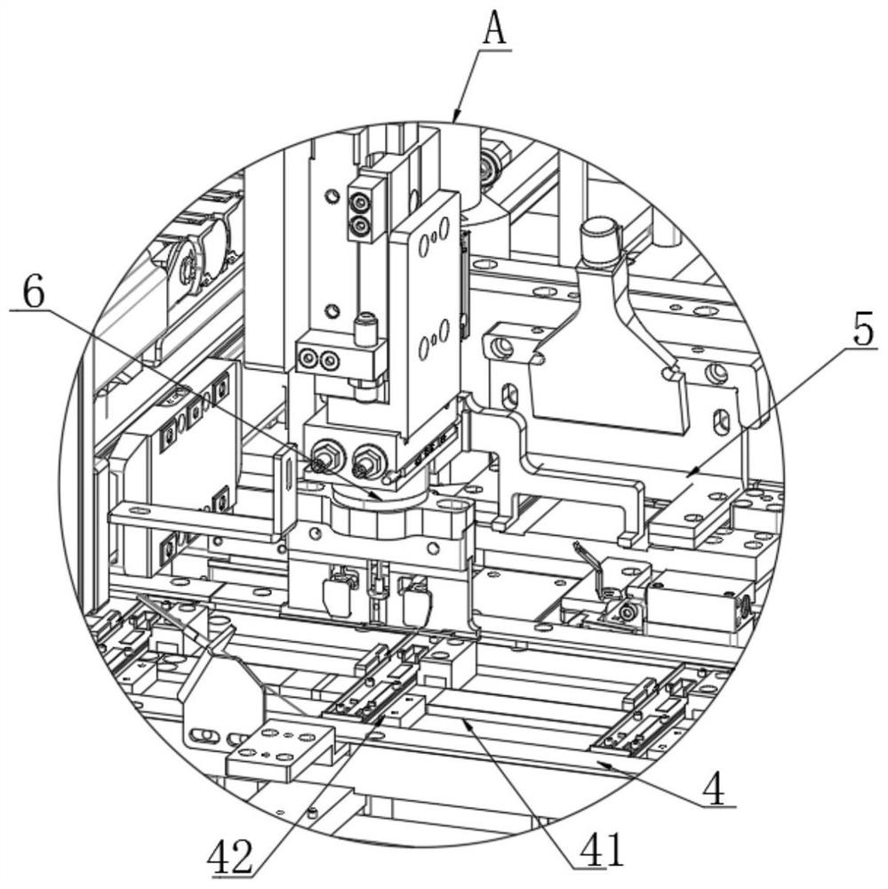
[0032] The present invention provides such Figure 1-8 A medical reagent card automatic assembly machine shown includes an assembly unit 1, and an upper shell feeder 2 and a lower shell feeder 3 are arranged on the outside of the assembly unit 1, and the upper shell feeder 2 and the lower shell feeder 3 The upper shell conveying device 21 and the lower shell conveying device 31 are respectively installed on the side close to the assembly unit 1, and the assembly conveying frame 4 is installed on the side of the assembly unit 1 away from the upper shell feeder 2 and the lower shell feeder 3 One end of the upper shell conveying device 21 and the lower shell conveying device 31 away from the upper shell feeder 2 and the lower shell feeder 3 runs thr...
PUM
 Abstract
Description
Claims
Application Information