Sludge dewatering device for pollution control

A technology for sludge dehydration and pollution prevention and control, which is applied in water/sludge/sewage treatment, sludge treatment, dehydration/drying/concentrated sludge treatment, etc. It can solve problems such as environmental pollution, disturbance, and long cycle time, and achieve guaranteed Filtration efficiency, fast dehydration treatment, and convenient disassembly and assembly

Inactive Publication Date: 2020-07-14
SHANGYU JINGLIDA AUTOMATION EQUIP
View PDF0 Cites 0 Cited by
  • Summary
  • Abstract
  • Description
  • Claims
  • Application Information

AI Technical Summary

Problems solved by technology

[0002] Due to insufficient anticipation of the negative impact of highly developed industries and poor prevention, three global crises have been caused: resource shortage, environmental pollution, and ecological damage. Environmental pollution refers to natural or man-made damage, adding certain substances to the environment And the behavior that causes harm beyond the self-purification ability of the environment, (or due to human factors, the environment is polluted by harmful substances, causing harmful effects on the growth and reproduction of organisms and the normal life of human beings,) the composition or state of the environment due to human factors Changes occur and the quality of the environment declines, thus disturbing and destroying the normal production and living conditions of the ecosystem and human beings
[0003] The existing technology has the following problems: in order to ensure that the sewage discharge meets the discharge standards and reduce the impact of impurities such as sludge in the sewage on the environment, a sedimentation method is usually used to make the impurities such as sludge in the sewage settle still, and then the upper layer The clear water and the lower sludge are pumped separately. This method not only has a long cycle, but also has low efficiency.

Method used


Image

  • Sludge dewatering device for pollution control
  • Sludge dewatering device for pollution control
  • Sludge dewatering device for pollution control

Examples


Embodiment Construction

[0026] The following will clearly and completely describe the technical solutions in the embodiments of the present invention with reference to the accompanying drawings in the embodiments of the present invention. Obviously, the described embodiments are only some, not all, embodiments of the present invention. Based on the embodiments of the present invention, all other embodiments obtained by persons of ordinary skill in the art without making creative efforts belong to the protection scope of the present invention.

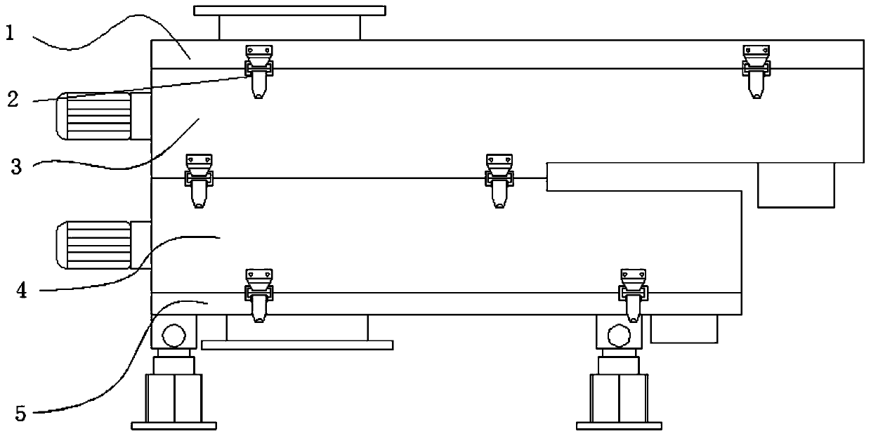
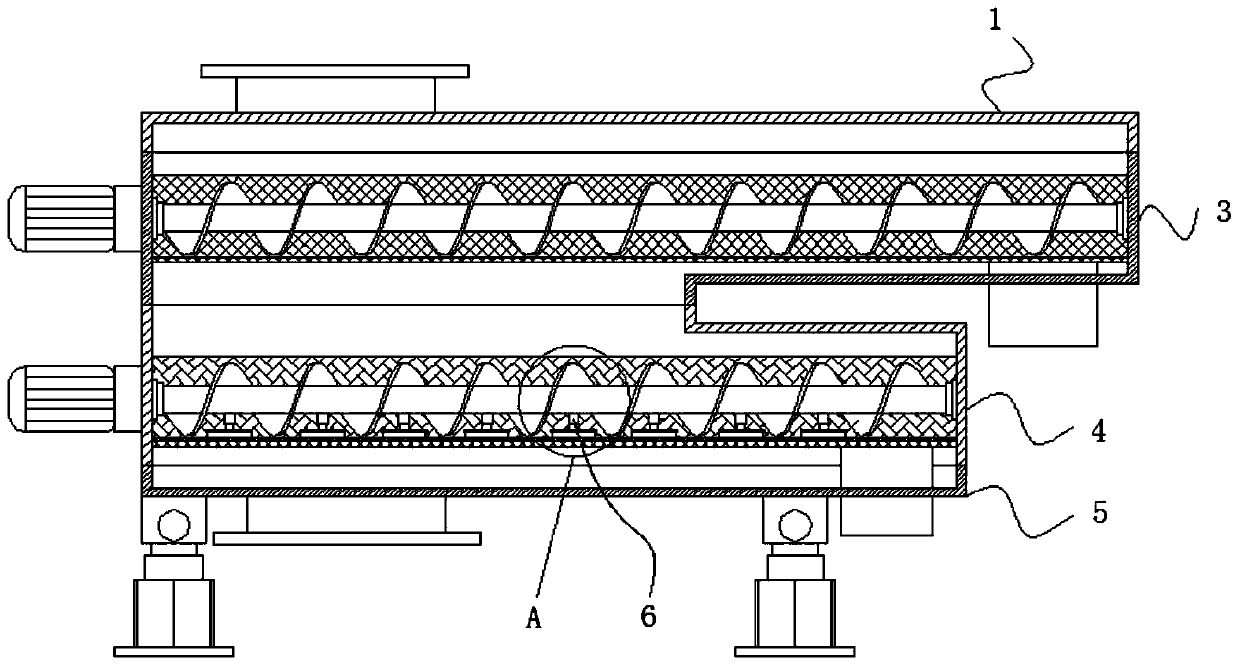
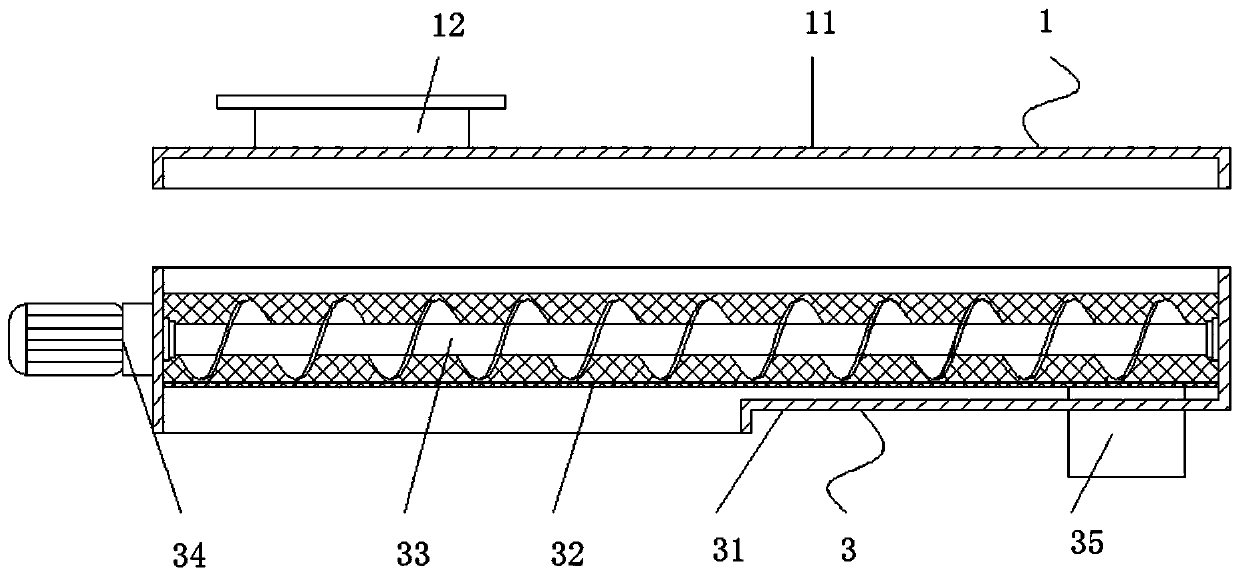
[0027] see Figure 1-7 , the present invention provides the following technical solutions: a sludge dewatering device for pollution prevention, including a sludge dewatering top cover assembly 1, and an impurity filter assembly 3 is fixedly arranged below the sludge dewatering top cover assembly 1 through an industrial hasp 2, and the impurity The bottom of the filter assembly 3 is fixed with a sludge filter assembly 4 through the industrial hasp 2, and the bo...


PUM


Abstract

The invention discloses a sludge dewatering device for pollution control. The device comprises a sludge dewatering top cover assembly, an impurity filtering assembly is fixedly arranged below the sludge dewatering top cover assembly through an industrial hasp; a sludge filtering assembly is fixedly arranged below the impurity filtering assembly through an industrial hasp; a sludge dewatering bottom box assembly is fixedly arranged below the sludge filtering assembly through an industrial hasp; a plurality of groups of jacking assemblies are fixedly arranged on a shaft rod of the sludge filtering assembly; large-particle stones or other impurities are filtered out through a semicircular impurity filtering screen in the impurity filtering assembly; when the primarily filtered sewage passes through the sludge filter cloth in the sludge filter assembly, sludge impurities contained in the sewage are filtered out, the filtered sludge is conveyed into the sludge discharge pipe through the sludge discharge spiral shaft rod, and a brush on the jacking assemblies abut against the sludge filter cloth on the inner side face of the semi-circular supporting net sieve plate through a jacking spring.

Description

technical field [0001] The invention belongs to the technical field of pollution prevention and control devices, and in particular relates to a sludge dewatering device for pollution prevention and control. Background technique [0002] Due to insufficient anticipation of the negative impact of highly developed industries and poor prevention, three global crises have been caused: resource shortage, environmental pollution, and ecological damage. Environmental pollution refers to natural or man-made damage, adding certain substances to the environment And the behavior that causes harm beyond the self-purification ability of the environment, (or due to human factors, the environment is polluted by harmful substances, causing harmful effects on the growth and reproduction of organisms and the normal life of human beings,) the composition or state of the environment due to human factors Changes occur and the quality of the environment declines, thereby disturbing and destroying ...

Claims


Application Information

Patent Timeline
Patent Type & Authority Applications(China)
IPC IPC(8): C02F11/14C02F11/125C02F11/00
CPCC02F11/00C02F11/125C02F11/14
Inventor 金宗良金泽雯陆益波
Owner SHANGYU JINGLIDA AUTOMATION EQUIP
Why Eureka
Try Eureka