Welding fixing frame for interface frame cable connector

A technology of cable connectors and fixing frames, which is applied in welding equipment, auxiliary welding equipment, welding/cutting auxiliary equipment, etc., can solve the problems of increasing welding operation difficulty, reducing production efficiency, and affecting welding quality, and achieves simple structure and improved Improve production efficiency and reduce the effect of false welding and false welding

Pending Publication Date: 2020-07-17
SHENYANG RAILWAY SIGNAL
View PDF0 Cites 2 Cited by
  • Summary
  • Abstract
  • Description
  • Claims
  • Application Information

AI Technical Summary

Problems solved by technology

The connector cannot be fixed during the soldering process, and it will move with the contact of the electric soldering iron during soldering, which not only increases the difficulty of the soldering operation, reduces production efficiency, but also has the possibility of false soldering, which has a great impact on the soldering quality

Method used


Image

  • Welding fixing frame for interface frame cable connector
  • Welding fixing frame for interface frame cable connector

Examples


Embodiment Construction

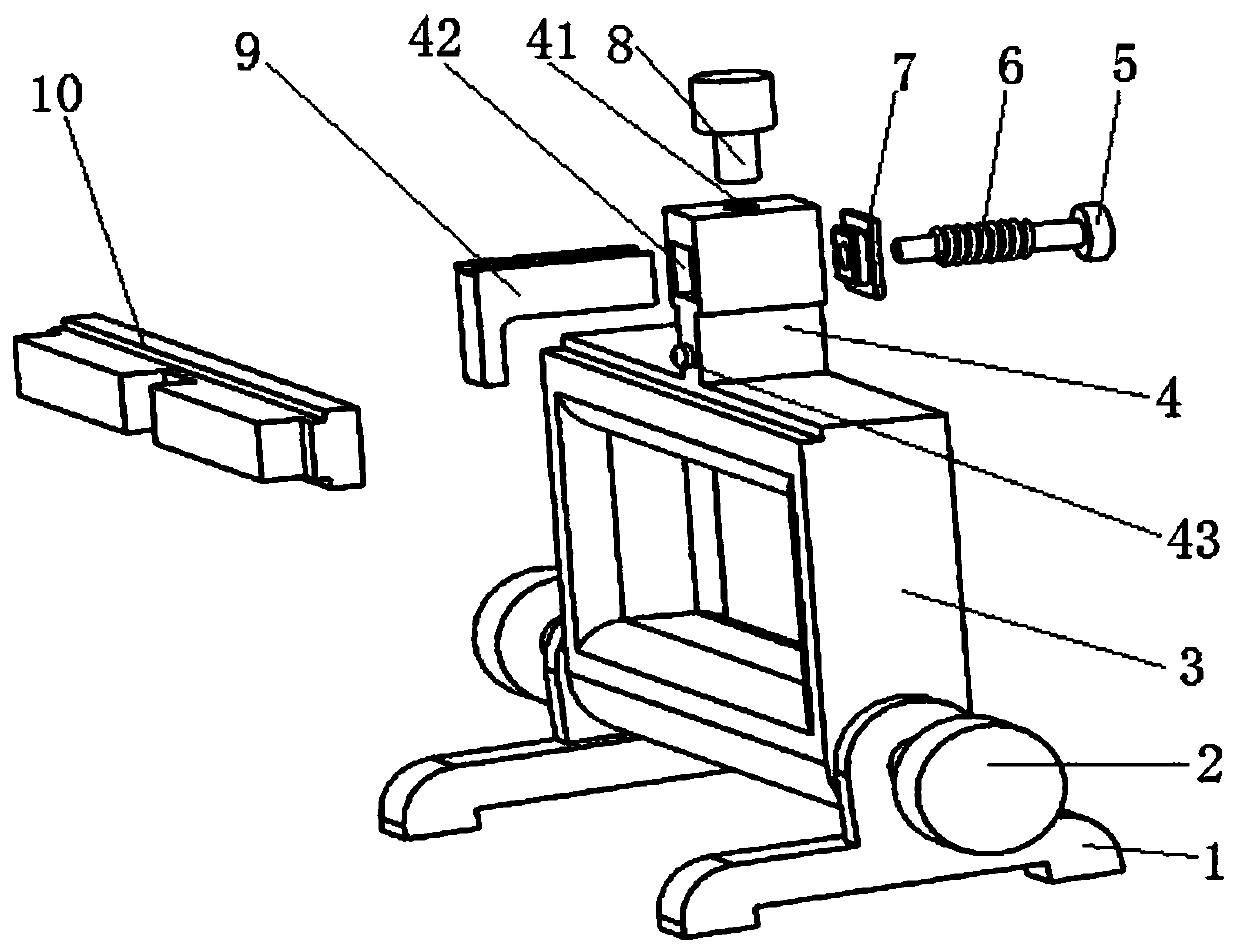
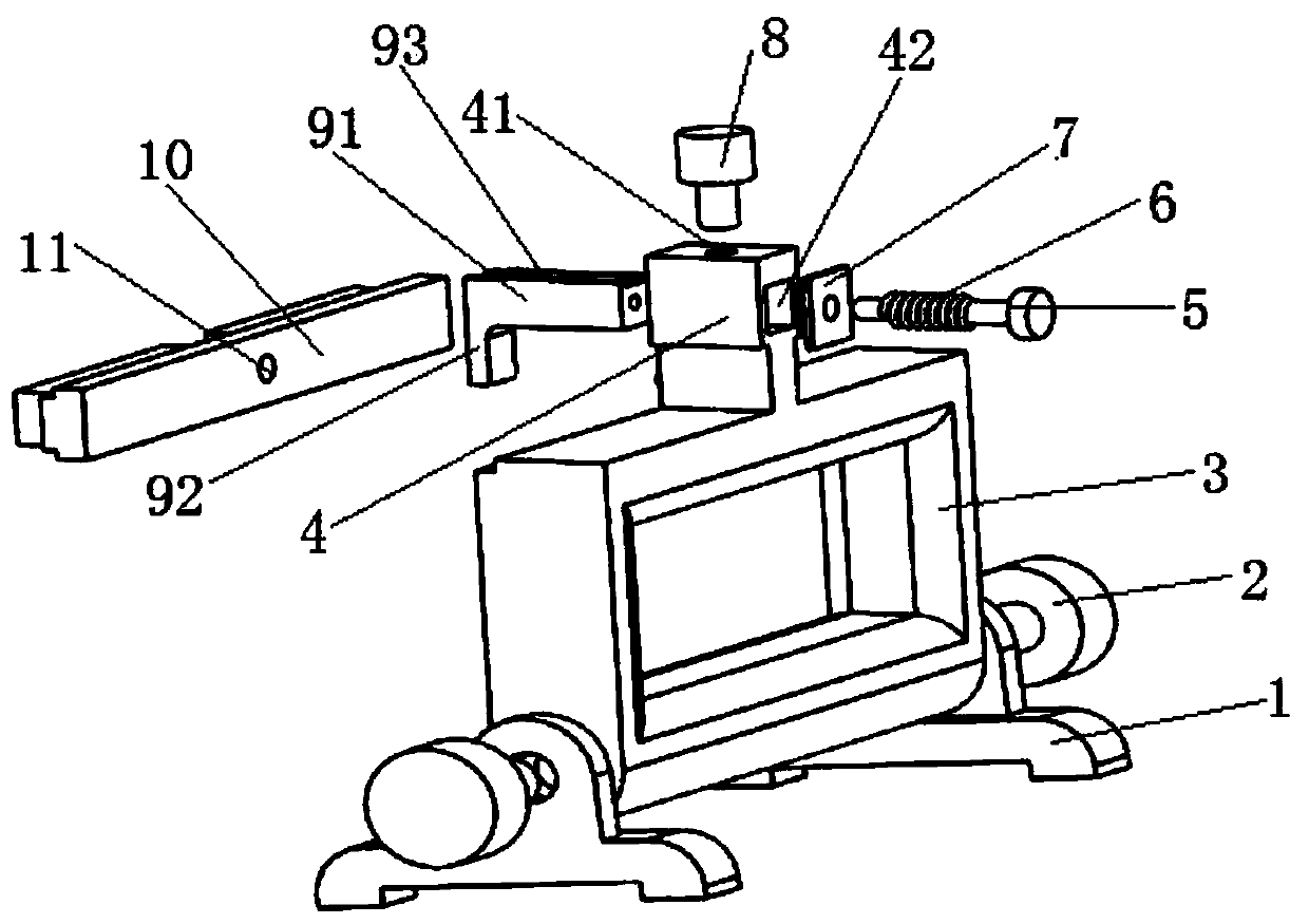
[0012] Such as figure 1 and 2 As shown, a welding fixing frame for an interface frame cable connector of the present invention includes: two legs 1, two locking nails 2, a welding frame 3, a clamp body 4, a connecting rod 5, a spring 6, and a baffle plate 7 , sliding clamp 9 and locking bolt 8.

[0013] The welding frame 3 is a rectangular frame, and two legs 1 are respectively fixed at both ends of the bottom of the welding frame 3 by two locking nails 2 . The fixture main body 4 is fixed on the top center of the welding frame 3 , the side of the fixture main body 4 is provided with a sliding channel 42 , and the top is provided with a locking screw hole 41 communicating with the sliding channel 42 . The sliding clip 9 includes a sliding part 91 and a clamping part 92 perpendicular to each other. The baffle plate 7 is covered at the entrance of one side of the sliding channel 42 . One side entrance protrudes. The connecting rod 5 passes through the through holes of the sp...


PUM


Abstract

The invention provides a welding fixing frame for an interface frame cable connector. The welding fixing frame comprises two supporting legs, two locking nails, a welding frame, a clamp main body, a link rod, a spring, a baffle plate, a sliding clamp and a locking bolt, wherein the welding frame is a rectangular frame; the two supporting legs are fixed to the two ends of the bottom of the weldingframe by locking nails; the clamp main body is fixed to the center of the top end of the welding frame; a sliding through slot is formed in the side surface of the clamp main body; a locking screw hole which is connected to the sliding through slot is formed in the top of the clamping main body; the sliding clamp comprises a sliding part and a clamping part; the baffle plate is used for covering the entrance of one side of the sliding through slot; the sliding part extends into the sliding through slot from the entrance of the other side of the sliding through slot; the link rod passes throughthe spring and a through hole of the baffle plate and is connected to the sliding part; the clamping part and the welding frame are matched to clamp the connector; and the locking bolt extends into the locking screw hole to compress the sliding clamp. When the welding fixing frame is used, the connector does not move easily, and an operator can choose the best welding angle for welding; and the welding fixing frame greatly improves the production efficiency and reduces the possibility of dry joint and false welding.

Description

technical field [0001] The invention belongs to the technical field of connector welding for cable products, and relates to a welding fixing frame for a cable connector of an interface frame. Background technique [0002] Cables are very common in signal transmission systems, such as drive cables, interface rack cables, etc., which are common in computer interlocking systems. At present, many cables are made by welding connection. The welding connector is characterized by small solder joints, large number and dense spots, which have high requirements on the welding level of the operator. The connector cannot be fixed during the welding process, and it will move with the contact of the electric soldering iron during welding, which not only increases the difficulty of the welding operation, reduces the production efficiency, but also has the possibility of false welding, which has a great impact on the welding quality. Contents of the invention [0003] In order to solve th...

Claims


Application Information

Patent Timeline
Patent Type & Authority Applications(China)
IPC IPC(8): B23K37/04
CPCB23K37/0426
Inventor 慕吉东李耀嫚李柏东郑海枫崔成彦赵书洋曹琳杨智清王建卜伟侯林琳黄志成
Owner SHENYANG RAILWAY SIGNAL
Why Eureka
Try Eureka