Stent and method for manufacturing same

A technology of circumferential direction and pattern, applied in the field of stent and stent manufacturing, can solve the problems of restenosis, reduced function, shortening, etc., and achieve the effect of reducing stent activity, improving expansion force, and preventing damage

Pending Publication Date: 2021-09-03
世运医疗股份有限公司
View PDF0 Cites 2 Cited by
  • Summary
  • Abstract
  • Description
  • Claims
  • Application Information

AI Technical Summary

Problems solved by technology

In particular, in conventional stents, in order to ensure expansion force, the crossing angle formed in the longitudinal direction Y is enlarged and the crossing angle formed in the circumferential direction X is reduced. Disadvantages of deployment position and difficult operation
[0009] In addition, once the stent is deployed, it cannot be moved, so if it is not placed accurately in the narrowed area, the function may be reduced or re-stenosis may occur, and in severe cases, there may be a problem of requiring reoperation

Method used


Image

  • Stent and method for manufacturing same
  • Stent and method for manufacturing same
  • Stent and method for manufacturing same

Examples


no. 2 example

[0089] Figure 7 The structure of the bracket of the second embodiment of the present invention is shown.

[0090] refer to Figure 7 The stent 1 of the second embodiment of the present invention can be applied in the same way as the above-mentioned first embodiment, but the only difference here is that the coating member 20 and the anti-movement members 31 and 32 are additionally used. Therefore, repeated descriptions will be omitted below, and descriptions will be given mainly for additional structures.

[0091] The stent 1 is coated with a coating member 20 such as polyurethane, which is used to cover the inner and outer surfaces of the stent 1, so that blood or Food etc. can flow smoothly.

[0092] The coating member 20 described above can be coated on the outer surface of the stent 1 while being heated to a predetermined temperature. In addition, the coating member 20 is formed by immersing the stent 1 in a melted tank and then cooling it to form a coating.

[0093] ...

no. 3 example

[0100] on the other hand, Figure 8 The grid structure of the stent of the third embodiment of the present invention is shown.

[0101] refer to Figure 8 , the stent 1 of the third embodiment of the present invention is similar to the above-mentioned embodiment, the difference lies in that it is configured to repeat the A-type prismatic pattern and the B-shaped prismatic pattern along the overall length direction Y with a predetermined interval and cycle. grid structure. That is, the stent 1 does not distinguish between the central part and both ends of the above-mentioned embodiment, but repeatedly forms the A section of the A-shaped prism pattern and the B section of the B-shaped prism pattern in the overall longitudinal direction Y. Morphological representation. Here, the predetermined interval and period are not limited to Figure 8 , but can be fabricated according to the arrangement design of the pins P of the jig 100 to change the structure.

[0102] Therefore, th...

no. 4 example

[0104] on the other hand, Figure 9 The grid structure of the stent of the fourth embodiment of the present invention is shown.

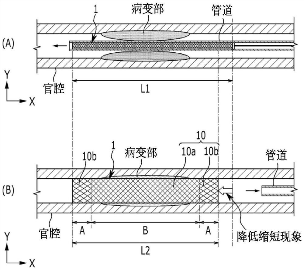
[0105] refer to Figure 9 , the stent 1 of the fourth embodiment of the present invention is similar to the above-mentioned embodiments, the difference lies in the grid structure formed in a continuous B-shaped prism pattern along the overall length direction Y. This has the effect of constituting a lattice structure capable of reducing the phenomenon of shortening of the stent 1 in an optimal state. Alternatively, with the Figure 4 to Figure 6 As explained above, the stent 1 is self-shrinkable and expandable, has flexibility, and forms the first unit part 11 and the second unit part 12 of the unit length respectively. The first turn and the second turn of the zigzag are respectively synthesized and woven to form a tight structure. pattern, so the expansion force can be maintained.


PUM


Abstract

A stent and a method for manufacturing the stent are disclosed. A stent according to an embodiment of the present invention is manufactured by using a jig having a cylindrical body on which a plurality of pins (P) are arranged in the circumferential direction (X) and the lengthwise direction (Y). The stent has a cylindrical structure, in which a wire member forms a zigzag pattern woven in the circumferential direction (X) with a predetermined width through the pins on the jig and a plurality of zigzag patterns formed in the circumferential direction (X), intersecting with one another, are arranged in the lengthwise direction with predetermined intervals (W) therebetween, forming a mesh structure with a rhombus pattern. The cylindrical structure has a dual-pattern structure, in which a first crossing angle of an A-type rhombus pattern formed at the central portion in the lengthwise direction (Y) is greater than a second crossing angle of a B-type rhombus pattern formed at opposite end portions of the structure in the lengthwise direction (Y).

Description

technical field [0001] The present invention relates to a stent and a method for making the stent, and more specifically, to a stent and a method for making the stent which minimizes the shortening phenomenon when the organ cavity is deployed. Background technique [0002] Generally, when the lumen of tubular structures such as arteries or digestive tracts in the body becomes narrow, blood or food cannot flow smoothly, which reduces function. The reduction in function is not only a disease of the lumen, but also directly or indirectly affects the circulatory system. [0003] Accordingly, if a patient's lumen is found to be narrow in a medical institution, a so-called stent operation is performed, and a stent is inserted into the lesion to expand the narrowed channel and maintain the expanded state. [0004] Usually, the stent has a cylindrical mesh structure, which has elastic force, shrinks when external force is applied, and expands when the external force is released. I...

Claims


Application Information

Patent Timeline
Patent Type & Authority Applications(China)
IPC IPC(8): A61F2/90A61F2/848A61F2/07
CPCA61F2/848A61F2/90A61F2250/0039A61F2240/001B21F45/008A61F2/07A61F2240/002A61F2230/0069A61F2220/0008A61F2/915A61F2002/91541A61F2002/91575A61F2220/0016
Inventor 李在姬许梦道金祥哲
Owner 世运医疗股份有限公司
Why Eureka
Try Eureka