Power monitoring containing pile and application method thereof

A power monitoring, monitoring and control technology, applied in separation methods, measuring device casings, chemical instruments and methods, etc., can solve the problems of poor flow conductivity of heat dissipation holes, heat generation, corrosion of internal parts, etc., to accelerate air circulation, improve Air circulation, improve the effect of heat dissipation

Active Publication Date: 2020-07-24
海南电网有限责任公司 +1
View PDF12 Cites 2 Cited by
  • Summary
  • Abstract
  • Description
  • Claims
  • Application Information

AI Technical Summary

Problems solved by technology

[0003] In the prior art, the real-time monitoring of power data for each power supply circuit or equipment is realized through the power monitoring equipment, and the power monitoring equipment can effectively monitor and repair the power supply loop, while the existing power monitoring equipment generally does not have protection functions , Power monitoring equipment will generate heat during operation, excessive heat will cause aging of power equipment components
[0004] In the prior art, heat dissipation holes are generally provided on the casing of the power monitoring equipment, and the flow conductivity of the heat dissipation holes is poor. When the outside air temperature is too high, a good heat dissipation effect cannot be achieved. In rainy days, There is also a large amount of water vapor in the introduced air. The air with water vapor is introduced into the casing, which will easily affect the normal operation of various parts inside the motor, and the internal parts will be strongly corroded.

Method used


Image

  • Power monitoring containing pile and application method thereof
  • Power monitoring containing pile and application method thereof
  • Power monitoring containing pile and application method thereof

Examples


Embodiment 1

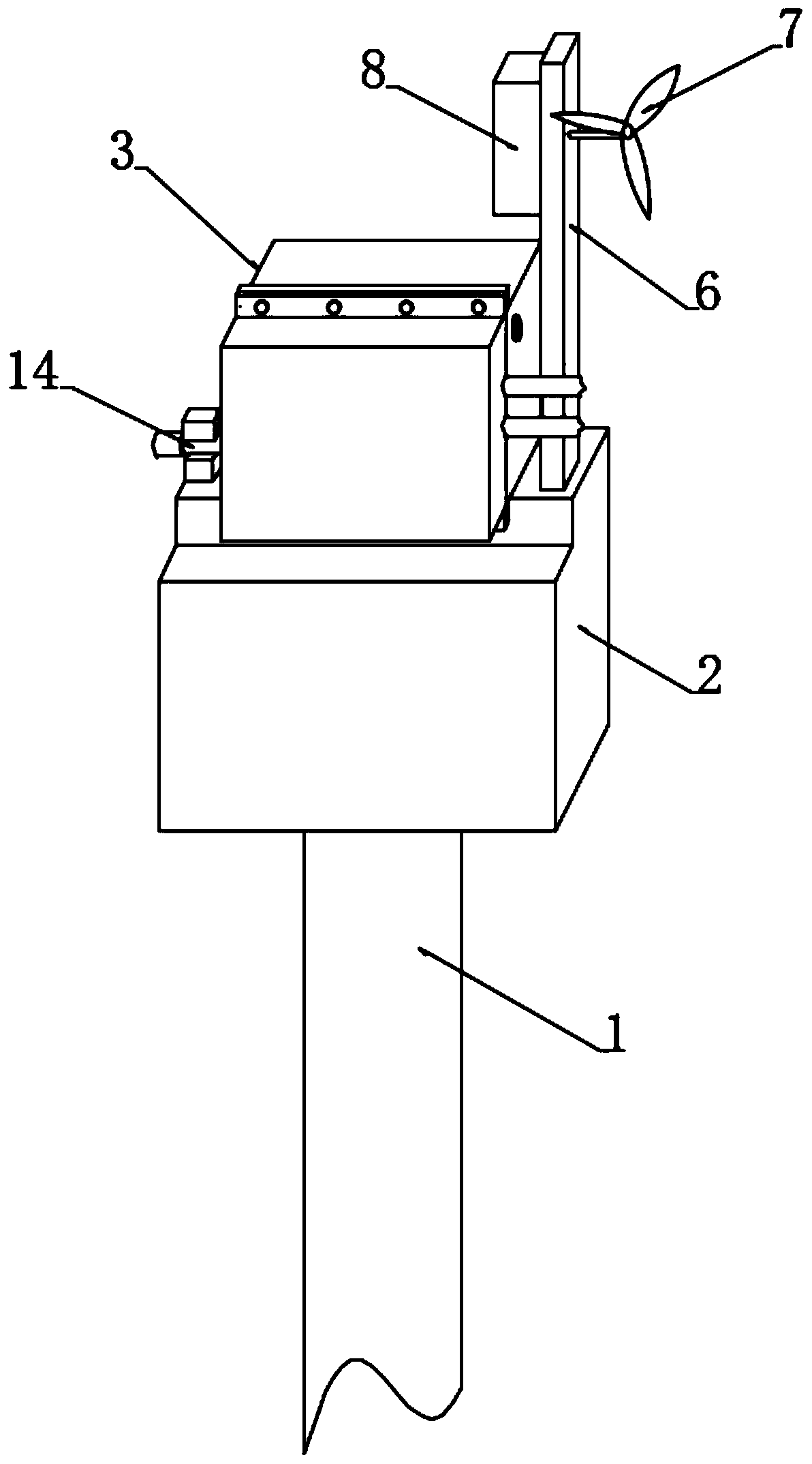
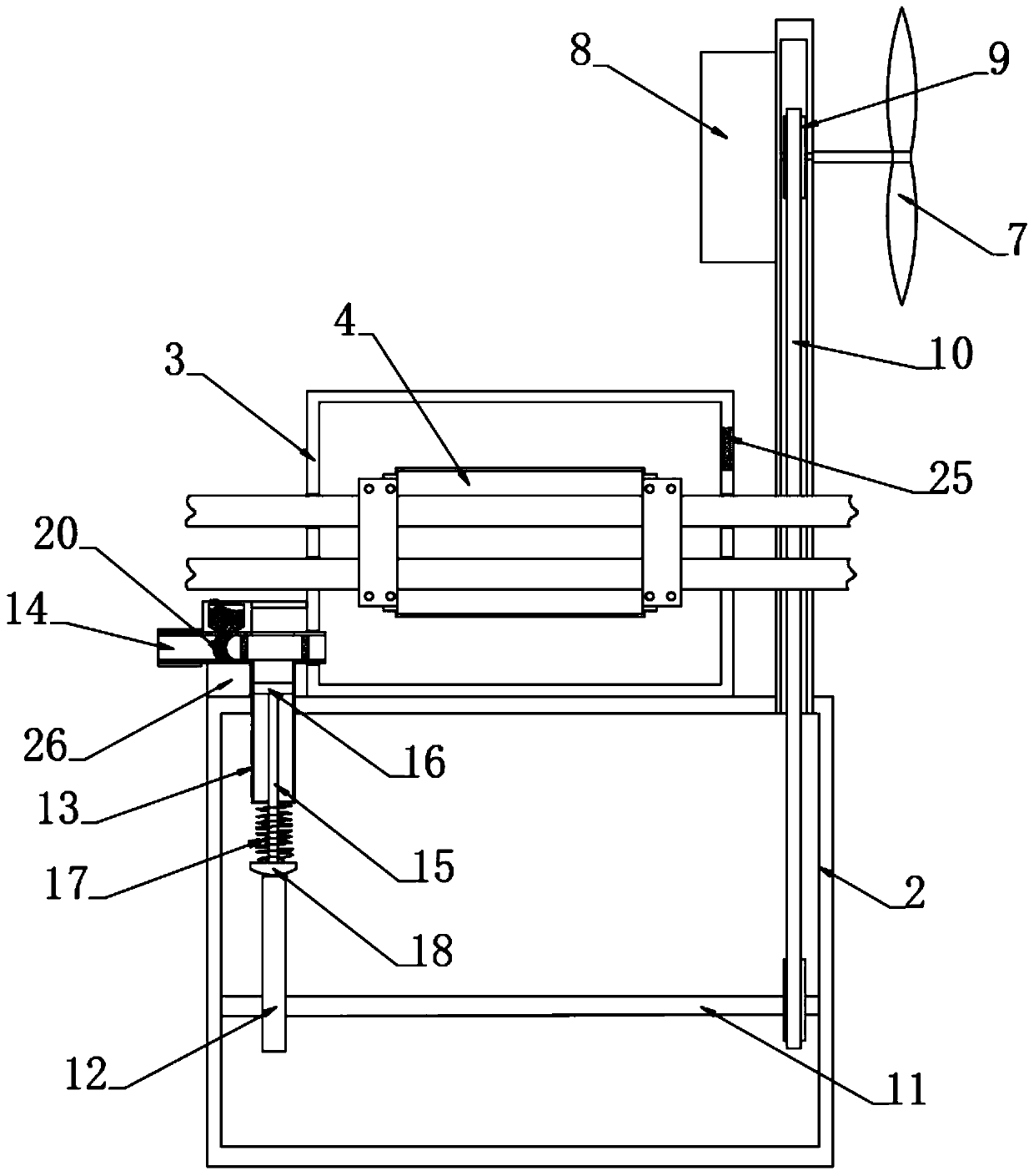
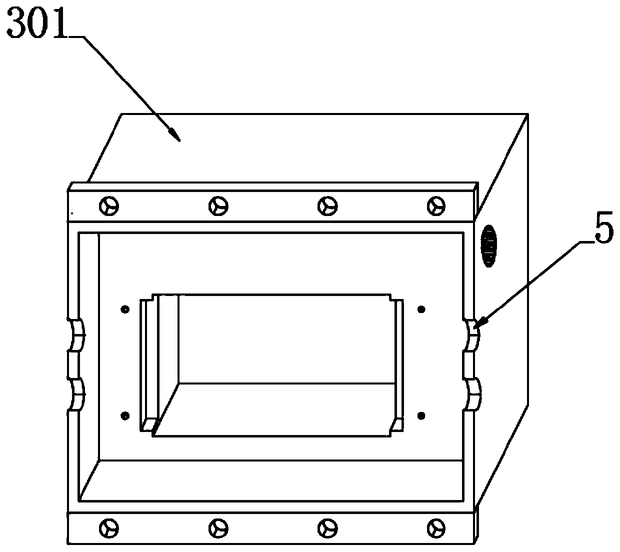
[0041] see figure 1 with Figure 3-5 , a power monitoring pile, including an operation box 2 fixedly connected to the top of the pile body 1, the upper end of the operation box 2 is fixedly connected with a monitoring control casing 3, and the two side walls of the monitoring control casing 3 are provided with holes for cable perforation The cable penetration hole 5, the monitoring device 4 for electrical monitoring of the cable is installed inside the monitoring and control housing 3, the monitoring and control housing 3 includes a left half shell 301 and a right half shell 302 that are docked, and the overall area of ​​the left half shell 301 is larger than The area of ​​the right half shell 302, the monitoring equipment 4 is installed in the left half shell 301, the inside of the left half shell 301 is provided with an installation cavity for the installation of the monitoring equipment 4, the left and right sides of the installation cavity are provided with positioning cav...


PUM


Abstract

The invention discloses a power monitoring containing pile and an application method thereof, and belongs to the technical field of power monitoring equipment. According to the power monitoring containing pile and the application method thereof, through cooperation of a windmill, a linkage mechanism and an air storage mechanism, outside air is continuously guided into a monitoring control shell through an air inlet pipe, ventilation is enhanced, and the heat radiation effect is improved; meanwhile, wind energy is converted into electric energy, natural wind is effectively utilized for controlling power of monitoring equipment or other controllers of the equipment, and energy output is saved; in addition, an outer port of the air inlet pipe is filled with a water absorption ball, moisture adsorption and removal are carried out on guided-in air, it is effectively guaranteed that circulating air is dry air, and the situation that equipment elements are influenced by moisture is avoided toa certain degree; and the left side and the right side of the water absorption ball are coated with high-porosity cooling layers, when the temperature of outside air is too high, hot steam is precooled, liquefied and cooled, and some water drops formed by liquidation can fully adsorb and dry the water absorption ball.

Description

technical field [0001] The invention relates to the technical field of electric power monitoring equipment, and more specifically, relates to a power monitoring placement pile and a method for using the same. Background technique [0002] In recent years, my country has implemented energy saving and consumption reduction as a major national policy, and the acquisition of electric energy data is the main source of energy data analysis. In order to achieve refined energy management and reduce costs and increase efficiency for enterprises, it is necessary to realize real-time monitoring of power data for each power supply circuit or equipment. [0003] In the prior art, the real-time monitoring of power data for each power supply circuit or equipment is realized through the power monitoring equipment, and the power monitoring equipment can effectively monitor and repair the power supply loop, while the existing power monitoring equipment generally does not have protection funct...

Claims


Application Information

Patent Timeline
Patent Type & Authority Applications(China)
IPC IPC(8): F03D9/11F03D17/00F03D80/80F03D9/17G01R1/04B01D53/26F16L59/02
CPCB01D53/261B01D53/265B01D2257/80F16L59/02F03D9/11F03D9/17F03D17/00F03D80/85G01R1/04Y02E10/72Y02E60/16Y02E70/30
Inventor 不公告发明人
Owner 海南电网有限责任公司
Why Eureka
Try Eureka