A hot rolling roller for asphalt road construction

A technology of road construction and hot rolling, which is applied in the field of hot rolling drums, can solve problems such as environmental pollution, high temperature of hot rolling drums, and low safety factor of charcoal, so as to increase storage space, reduce replacement frequency, and improve utilization rate Effect

Active Publication Date: 2021-11-02
枣庄旗胜建设集团有限公司
View PDF0 Cites 0 Cited by
  • Summary
  • Abstract
  • Description
  • Claims
  • Application Information

AI Technical Summary

Problems solved by technology

[0003] The purpose of the present invention is to provide a hot rolling roller for asphalt road construction, which is used to solve the problem that the burnt charcoal in the heating core needs to be stopped for cleaning along with the construction of the hot rolling roller. During this process, it cannot Realize the continuous operation of the hot rolling drum, and the internal temperature of the hot rolling drum is high. At this time, the safety factor of replacing charcoal is not only low, but also the carbon ash is easy to volatilize into the environment, causing technical problems of environmental pollution

Method used


Image

  • A hot rolling roller for asphalt road construction
  • A hot rolling roller for asphalt road construction
  • A hot rolling roller for asphalt road construction

Examples


Embodiment 1

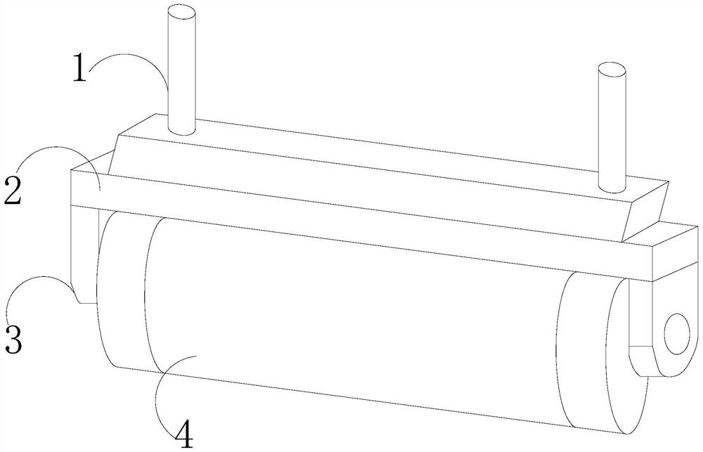
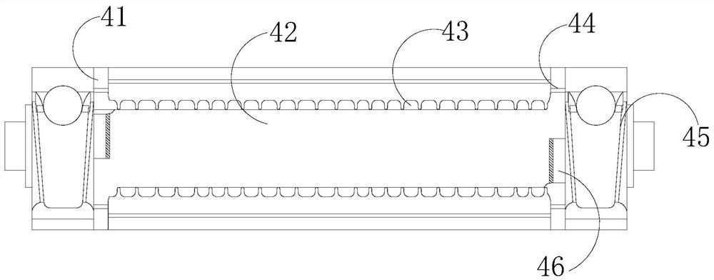
[0032] Such as Figure 1-Figure 4 As shown, the present invention provides a hot rolling roller for asphalt road construction. Its structure includes a vertical rod 1, an installation frame 2, a fixed head 3, and a cylinder body 4. The cylinder body 4 is mechanically connected by the fixed head 3 and the installation frame 2 The installation frame 2 is installed on the walking device through the two vertical poles 1 vertically fixed on the upper end, and the cylinder body 4 includes a feeding port 41, a heating core 42, a cooling hole 43, a discharge port 44, and a collector. Material mechanism 45, self-propelled scraper 46, described feeding port 41 and discharging port 44 are communicated with heating core 42, and described heating core 42 is provided with more than two cooling holes 43, on described heating core 42 A slideway cooperating with the self-propelled scraper 46 is provided, and the self-propelled scraper 46 is horizontally movable and matched with the discharge p...

Embodiment 2

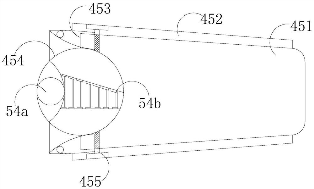
[0039] Such as Figure 5-Figure 7 As shown, on the basis of Embodiment 1, through the mutual cooperation of the following structural components, the air guide mechanism 54c includes an air pump c1 and an air delivery pipe c2, the gas outlet of the air pump c1 is connected to the air delivery pipe c2, and the air delivery pipe There are more than two c2, which are connected to the crushing chamber 54b in an arched shape.

[0040] The crushing cavity 54b includes a support plate 4b1, a slide bar 4b2, and a broken block 4b3. The inside of the support plate 4b1 is fixed with a slide bar 4b2. Both ends of the slide bar 4b2 are respectively provided with a broken block 4b3. 4b3 moves in the same direction along the slide bar 4b2 to change the spacing, thereby realizing the crushing effect on the charcoal output from the discharge port 54a.

[0041] The broken block 4b3 is equipped with a sealed air bag b31, and more than two barbs b32 are densely covered on the surface of the broke...


PUM


Abstract

The invention discloses a hot rolling roller for asphalt road construction. Its structure includes a vertical rod, a mounting frame, a fixing head and a cylinder body. The cylinder body is mechanically connected with the installation frame through the fixing head. The vertical pole is installed on the walking device. The cylinder body includes a feeding port, a heating core, a heat dissipation hole, a material outlet, a material collecting mechanism, and a self-propelled scraper. The feeding port and the material outlet are connected to the heating core. There are more than two heat dissipation holes, and the heating core is provided with a slideway that cooperates with the self-propelled scraper. During the rolling of the cylinder body of the present invention, due to the effect of the center of gravity, the lower layer where the remaining material is concentrated, so there is a heating core in the heating core. The feed port and discharge port are arranged in an X shape, so that no matter how it rolls, there is a discharge port located on the lower layer, so that the remaining material in the heating core can be effectively discharged, and the self-propelled scraper is used to discharge the heating core during discharge. The residue on the inner wall can also be scraped clean, avoiding the mixing of new and old materials to affect combustion.

Description

technical field [0001] The invention relates to the technical field of road construction, in particular to a hot rolling roller for asphalt road construction. Background technique [0002] In the construction process of paving asphalt roads, asphalt floor hot rolling rollers are usually used to roll and level the road surface to achieve a certain degree of flatness. The main structure of the existing asphalt floor hot rolling rollers is a metal The hollow cylinder is used as the outer drum, and there is a closed hollow semi-cylindrical inner heating core inside the outer drum. There are many heat dissipation holes on the inner heating core, and a shaft is welded at both ends of the inner heating core and passes through it. Due to the effect of the center of gravity on the central hole of the end cover of the outer drum and the outside of the push handle, the opening of the heating core is always upward. During construction, the burning charcoal is first placed in the inner h...

Claims


Application Information

Patent Timeline
Patent Type & Authority Patents(China)
IPC IPC(8): E01C19/23
CPCE01C19/23E01C19/236
Inventor 李冬杰
Owner 枣庄旗胜建设集团有限公司
Why Eureka
Try Eureka