Injection mold head

A technology for injection molds and mold heads, which is applied in the field of molds and can solve problems such as deviation of plastic cooling time and quality impact of plastic products

Inactive Publication Date: 2020-09-22
广州优易机械科技有限公司
View PDF0 Cites 0 Cited by
  • Summary
  • Abstract
  • Description
  • Claims
  • Application Information

AI Technical Summary

Problems solved by technology

[0003] When the injection head is injecting into a mold with a small volume, it is easy to quickly fill up the molten plastic inside the mold, and reversely squeeze into the injection head before the injection head is pulled out, resulting in a molten state that is extruded again The cooling time of the plastic is deviated, so that it is difficult to control the cooling time of the plastic, which easily affects the quality of the plastic product

Method used


Image

  • Injection mold head
  • Injection mold head
  • Injection mold head

Examples


Embodiment 1

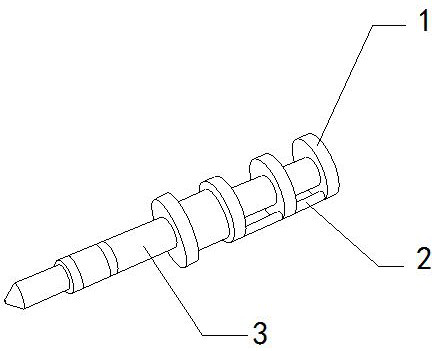
[0026] For example figure 1 -example Figure 5 Shown:

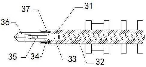
[0027] The present invention provides a die head of an injection mold, the structure of which includes a connecting end 1, a stabilizing rod 2, and an extrusion head 3. The stabilizing rod 2 is embedded and connected to the connecting end 1. Integrated structure; the extrusion head 3 includes a pipe body 31, a screw push rod 32, a booster rod 33, a connecting column 34, a joint block 35, an extrusion mechanism 36, and an elastic strip 37. The screw push rod 32 is connected to the tube The body 31 is threaded, the booster rod 33 is welded to the front end of the screw push rod 32, one end of the connecting column 34 is embedded and connected with the joint block 35, and the other end of the connecting column 34 is in clearance fit with the pipe body 31, The combination block 35 and the pipe body 31 are of an integrated structure, the extruding mechanism 36 is installed at the front end of the combination block 35 , and t...

Embodiment 2

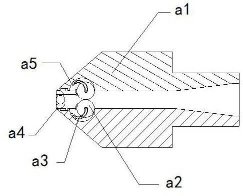
[0034] For example Figure 6 -example Figure 8 Shown:

[0035] Wherein, the clearing mechanism b5 includes an ejector block b51, a telescopic plate b52, an outer ring b53, a pull bar b54, a linkage rod b55, a guide frame b56, and an inner ring b57, and the ejector block b51 and the telescopic plate b52 are integrated structure, the telescopic plate b52 is movably engaged with the guide frame b56, the outer ring b53 is fixed at the outer position of a57, the pull bar b54 is installed at the inner position of the outer ring b53, and one end of the linkage rod b55 is connected to the telescopic The plate b52 is embedded and connected, and the other end of the linkage rod b55 is in clearance fit with the outer ring b53. The guide frame b56 is embedded in the inner position of the inner ring b57. Evenly distributed in a circular shape on the guide frame b56, when the external plastic solution is squeezed in, the mechanism will be squeezed, and the mechanism can be bent, so that ...


PUM


Abstract

The invention discloses an injection mold head. The injection mold head structurally comprises a connecting end, a stabilizing rod and an extrusion head, the stabilizing rod is fixedly connected withthe connecting end in an embedded mode, and the extrusion head and the connecting end are of an integrated structure. According to the injection mold head, extrusion plates can generate thrust to linkage blocks through thrust generated by an extruded plastic solution to the extrusion plates on a middle receiving ball so that the linkage blocks can drive extending strips to slide out along connecting frames while sliding outwards along the extrusion plates, then the tops of the extending strips can abut against the outer walls of contact blocks, and then the middle receiving ball cannot rotate;and when the external plastic solution stops being extruded inwards, linkage rods are pulled through pulling strips on a removing mechanism so that the linkage rods can drive telescopic plates to slide outwards along guide frames, then ejection blocks can push the rear ends of the extrusion plates to be lifted upwards, and then the extrusion plates can push down the plastic solution staying between the extrusion plates and outer fixing blocks.

Description

technical field [0001] The invention relates to the field of molds, in particular to a mold head of an injection mold. Background technique [0002] The injection mold head is mainly the equipment installed at the front end of the screw push rod on the injection molding machine. It can extend into the injection port on the mold to squeeze the molten plastic conducted by the screw push rod into the mold, and the injection mold head will squeeze the molten plastic into the mold. When extruding into the mold, the front head needs to extend into the mold, so it is necessary to control the injection time, pull out the injection head when the mold is about to be filled, and continue to squeeze in through the process of pulling out the injection head Filling the mold with plastic solution is common equipment in the plastic mold processing industry. Based on the above description, the inventors found that the existing injection mold head mainly has the following deficiencies, such a...

Claims


Application Information

Patent Timeline
Patent Type & Authority Applications(China)
IPC IPC(8): B29C45/20B29C45/24
CPCB29C45/20B29C45/24
Inventor 宋余平
Owner 广州优易机械科技有限公司
Why Eureka
Try Eureka