LED driving power supply

A technology of LED drive and DC power supply, applied in the direction of electrical components, etc., which can solve the problems of large parasitic capacitance between circuit board and metal layer, increased cost, harmful stroboscopic problems of eyes, etc.

Pending Publication Date: 2020-11-03
MORNSUN GUANGZHOU SCI & TECH
View PDF1 Cites 0 Cited by
  • Summary
  • Abstract
  • Description
  • Claims
  • Application Information

AI Technical Summary

Problems solved by technology

[0004] 1. If the AC rectifier is connected to the LED load, during the period from the low input voltage to the zero crossing of the input voltage, the LED load will have no current flow, which will cause the LED to emit light intermittently, which will cause damage to the eyes. Strobe problem;
[0005] 2. If the AC rectifier is filtered by the filter capacitor and then connected to the LED load, the above flickering problem can be solved, but the power factor of this solution is very low;
[0006] 3. With the continuous improvement of the power of LED lamps, the high-power LED driver uses an aluminum substrate as a circuit board, which can dissipate heat well, but this solution will generate a large parasitic capacitance between the circuit board and the metal layer
However, this solution requires an additional switch tube and drive circuit, which makes the control complex and requires additional cost

Method used


Image

  • LED driving power supply
  • LED driving power supply
  • LED driving power supply

Examples


no. 1 example

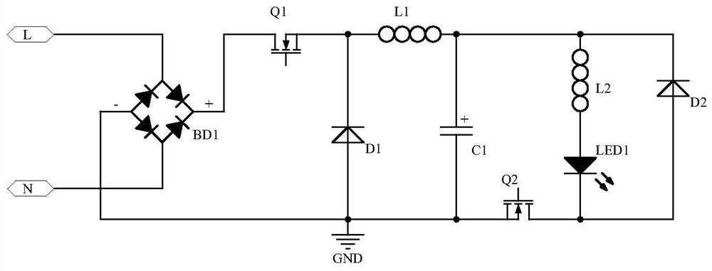
[0056] image 3 For the circuit principle of the first embodiment of the present invention, for figure 1 a specific circuit.

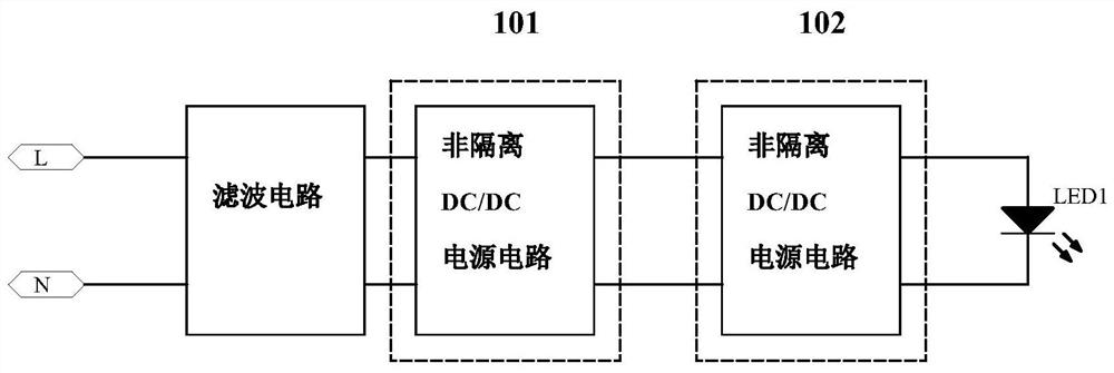
[0057] The filter circuit is a rectifier bridge BD1, the positive input terminal of the rectifier bridge BD1 is used to connect to the L line of the grid, the negative input terminal is used to connect to the N line of the grid, and the positive output terminal is connected to the positive input terminal of the non-isolated DC / DC power supply circuit 101, The negative output terminal is connected to the negative input terminal of the non-isolated DC / DC power supply circuit 101;

[0058] The non-isolated DC / DC power supply circuit 101 is a buck circuit, including a switch tube Q1, a diode D1, an inductor L1, and a capacitor C1. The drain of the switch tube Q1 is the positive input terminal of the non-isolated DC / DC power supply circuit 101, and the source of the switch tube Q1 is One end of the inductance L1 is connected to the cathode of the diode D1...

no. 2 example

[0069] Figure 4 It is the circuit principle of the second embodiment of the present invention, and the difference from the first embodiment is that the non-isolated DC / DC power supply circuit 101 is a BUCK-BOOST circuit, including a switch tube Q1, a diode D1, an inductor L1 and a capacitor C1, and a switch The drain of the tube Q1 is the positive input terminal of the non-isolated DC / DC power supply circuit 101, the source of the switch tube Q1 is connected to one end of the inductor L1 and the cathode of the diode D1 at the same time, and the anode of the diode D1 is connected to one end of the capacitor C1 to be non-isolated. The positive output end of the DC / DC power supply circuit 101, the other end of the inductor L1 and the other end of the capacitor C1 are connected to both the negative input end of the non-isolated DC / DC power supply circuit 101 and the negative output of the non-isolated DC / DC power supply circuit 101 end.

[0070] The working principle of this emb...

no. 3 example

[0078] Figure 5 It is the circuit principle of the third embodiment of the present invention. The difference between this embodiment and the second embodiment is that the non-isolated DC / DC power supply circuit 102 is a BUCK circuit, including a switch tube Q2, a diode D2, an inductor L2 and a capacitor C2. After the anode of the diode D2 is connected to one end of the capacitor C2, it is simultaneously the positive input terminal of the non-isolated DC / DC power supply circuit 102 and the positive output terminal of the non-isolated DC / DC power supply circuit 102, and the cathode of the diode D2 is simultaneously connected to the source of the switch tube Q2 pole and one end of the inductor L2, the drain of the switch tube Q2 is the negative input end of the non-isolated DC / DC power supply circuit 102, and the other end of the inductor L2 is the negative output end of the non-isolated DC / DC power supply circuit 102.

[0079] The working principle of this embodiment is as foll...


PUM


Abstract

The invention discloses an LED driving power supply which comprises a filter circuit, a first non-isolated DC/DC power supply circuit and a second non-isolated DC/DC power supply circuit which are connected in sequence. The main power switch tubes in the first non-isolated DC/DC power supply circuit and the second non-isolated DC/DC power supply circuit are arranged on a bus, one is arranged at ahigh-voltage end, and the other is arranged at a low-voltage end. Under the condition that the cost is not increased, the main power switch tube in the non-isolated DC/DC power supply circuit not onlymeets the normal work of the LED driving power supply, but also blocks the electric leakage of the LED driving power supply, so that the problem that the dimmable LED driving power supply in the prior art cannot truly realize the dimming turn-off function is solved; in addition, the stroboflash problem of the LED driving power supply can be effectively solved, the PF value is increased, the lossis reduced, and the input and output range of the LED driving power supply is wide.

Description

technical field [0001] The present application relates to the technical field of lighting control, and more specifically, to an LED driving power supply with a function of dimming and shutting off. Background technique [0002] With the development of technology, the field of LED light source puts forward higher requirements for energy saving, and it is necessary to reduce the power loss of LED driving power as much as possible under the premise of meeting the illumination. In this context, a dimmable LED drive power supply has appeared on the market. This type of power supply can adjust the brightness of the LED light according to the demand and reduce unnecessary loss. Such as 0-10V dimming, timing dimming and other dimmable LED driver power supply, and LED driver power supply with dimming shutdown function. [0003] The existing dimmable LED drive power supply has the following disadvantages: [0004] 1. If the AC rectifier is connected to the LED load, during the perio...

Claims


Application Information

Patent Timeline
Patent Type & Authority Applications(China)
IPC IPC(8): H05B45/30H05B45/10
CPCH05B45/10H05B45/30
Inventor 尹向阳符恩亮周灿荣
Owner MORNSUN GUANGZHOU SCI & TECH
Why Eureka
Try Eureka