Top-drive guide rail assembly and top-drive guide rail system

A technology of top drive guide rails and components, which is used in earth-moving drilling, support devices, drilling equipment, etc., to achieve the effect of ensuring stability, stable rail connection, and stable connection

Inactive Publication Date: 2017-03-22
SINOPEC ZHONGYUAN PETROLEUM ENG CO LTD
View PDF8 Cites 2 Cited by
  • Summary
  • Abstract
  • Description
  • Claims
  • Application Information

AI Technical Summary

Problems solved by technology

[0004] The purpose of the present invention is to solve the above problems, to provide a top drive guide rail assembly, the connection between two adjacent sets of guide rail units is more stable, so that the connectors are not easy to withdraw, to ensure the stability of the guide rail connection, so that the above problems are improved

Method used


Image

  • Top-drive guide rail assembly and top-drive guide rail system
  • Top-drive guide rail assembly and top-drive guide rail system
  • Top-drive guide rail assembly and top-drive guide rail system

Examples


no. 1 example

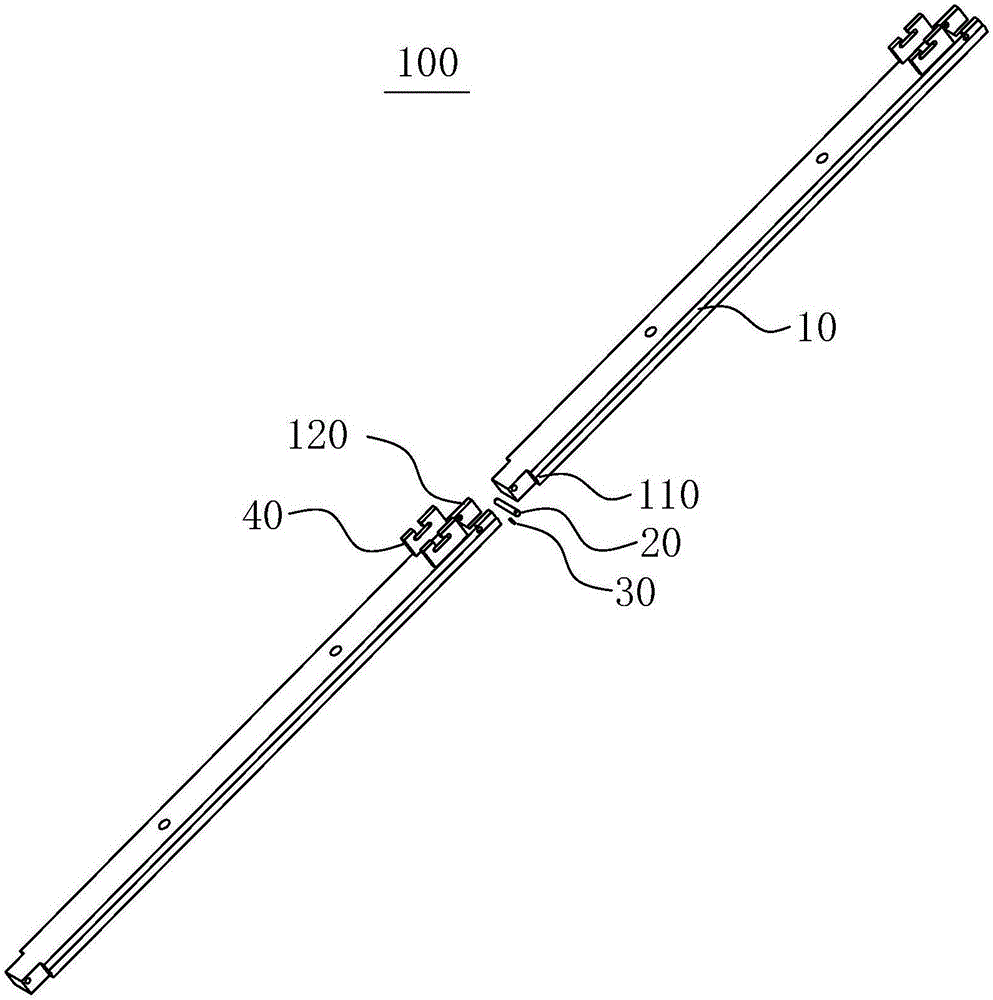
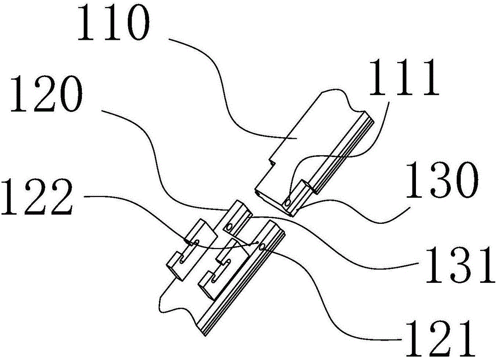
[0036] Please refer to figure 1 , the present embodiment provides a top drive guide rail assembly 100, including a connector 20, a stopper 30 and at least two groups of guide rail units 10, two adjacent groups of guide rail units 10 are connected by the connector 20 and form a connection portion, the connection portion It includes a first connection part 110 and a second connection part 120 , and the first connection part 110 is plugged into the second connection part 120 . It should be pointed out that the first connecting portion 110 and the second connecting portion 120 are respectively located in two adjacent sets of guide rail units 10 .

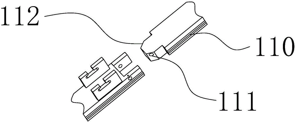
[0037] Such as figure 2As shown, the end of the first connecting portion 110 has a chamfered portion 112, and the chamfered portion 112 is located at the two end faces of the guide rail unit 10 in the width direction, that is, at both ends of the end of the first connecting portion 110 away from the guide rail unit 10. The side is ch...

no. 2 example

[0052] Please refer to Figure 7 , this embodiment provides a top drive guide rail system, including the anti-torque bracket 510, the top drive guide rail hanger 520 and the top drive guide rail assembly 100 provided in the first embodiment, and the rest of the unmentioned parts refer to the first embodiment or existing technology.

[0053] In this embodiment, the top drive rail assembly 100 is connected to the top drive rail suspension frame 520 , and the anti-torque bracket 510 is connected to the top drive rail assembly 100 .

[0054] Further, the top drive guide rail suspension frame 520 includes a guide rail lug and an adjustment plate 530, the guide rail lug is fixed on the bottom plate of the crown block, the adjustment plate 530 and the guide rail lug are connected by a U-shaped ring, and the adjustment plate 530 is connected to the top drive guide rail assembly 100 connect. Such as Figure 8 As shown, the adjustment plate 530 includes an adjustment plate body, a fi...


PUM


Abstract

The invention relates to a top-drive guide rail assembly and a top-drive guide rail system and belongs to the technical field of petroleum machinery. The top-drive guide rail assembly comprises connecting parts, limiting parts and at least two guide rail units. Every two adjacent guide rail units are connected through the corresponding connecting part to form a connecting portion which comprises a first connecting portion body and a second connecting portion body, wherein the first connecting portion body is connected to the second connecting portion body in an inserted mode, and the first connecting portion body and the second connecting portion body are connected through the corresponding connecting part; and the second connecting portion body is provided with a thread limiting hole, and the corresponding limiting part penetrates in the thread limiting hole and abuts against the corresponding connecting part. According to the top-drive guide rail assembly, every two adjacent guide rail units are connected more firmly, and guide rail connection stability is guaranteed. The top-drive guide rail system comprises the top-drive guide rail assembly, guide rail connection for the system is stable, and normal work of top-drive guide rails can be met.

Description

technical field [0001] The invention relates to the technical field of petroleum machinery, in particular to a top drive guide rail assembly and a top drive guide rail system. Background technique [0002] In the process of oil and gas exploration and production, the oil drilling top drive equipment (referred to as top drive) is hung on the traveling car of the drilling rig. As an indispensable part of the top drive equipment, the guide rail not only enables the top drive It slides up and down, and can withstand the reaction torque of the top drive driven drill pipe during rotary drilling, make-up and breakout. [0003] At present, in the top drive drilling equipment at home and abroad, the installation and connection of the guide rail is mainly connected by the pin shaft. In the pin shaft matching of the existing guide rail, the movement of the pin shaft is mainly limited by the limit groove in the middle of the pin shaft. Because the pin shaft matching structure of the gu...

Claims


Application Information

Patent Timeline
Patent Type & Authority Applications(China)
IPC IPC(8): E21B15/00
CPCE21B15/003
Inventor 张怀刘再予张永涛郑明艳刘松姬未来
Owner SINOPEC ZHONGYUAN PETROLEUM ENG CO LTD
Why Eureka
Try Eureka