Eureka AIR delivers breakthrough ideas for toughest innovation challenges, trusted by R&D personnel around the world.

Mine electric power electrical distribution cabinet with good dust removal performance

A technology for electric power and power distribution cabinets, which is applied to the substation/power distribution device shell, electrical components, substation/switch layout details, etc. It can solve problems such as single function, simple design structure, and influence on the heat dissipation of power distribution cabinets, so as to avoid Dust pollution, guaranteed performance, good protection effect

Inactive Publication Date: 2018-11-13
肇庆中能创智信息科技有限公司
View PDF11 Cites 2 Cited by
  • Summary
  • Abstract
  • Description
  • Claims
  • Application Information

AI Technical Summary

Problems solved by technology

The above-mentioned patents have the following deficiencies: it cannot ensure that the power distribution cabinet has a good dust-proof effect during the working process, which affects the normal operation of the power distribution cabinet, and the space inside the power distribution cabinet does not have the function of adjustment, which will also affect Heat dissipation when the power distribution cabinet is working, the design structure is simple, the function is single, and it is inconvenient to use
And above-mentioned patent can't solve this kind of problem, therefore, need badly a kind of mine with good dust-removing property electric distribution cabinet

Method used


Image

  • Mine electric power electrical distribution cabinet with good dust removal performance
  • Mine electric power electrical distribution cabinet with good dust removal performance
  • Mine electric power electrical distribution cabinet with good dust removal performance

Examples


Embodiment Construction

[0026] The following will clearly and completely describe the technical solutions in the embodiments of the present invention with reference to the accompanying drawings in the embodiments of the present invention. Obviously, the described embodiments are only some, not all, embodiments of the present invention.

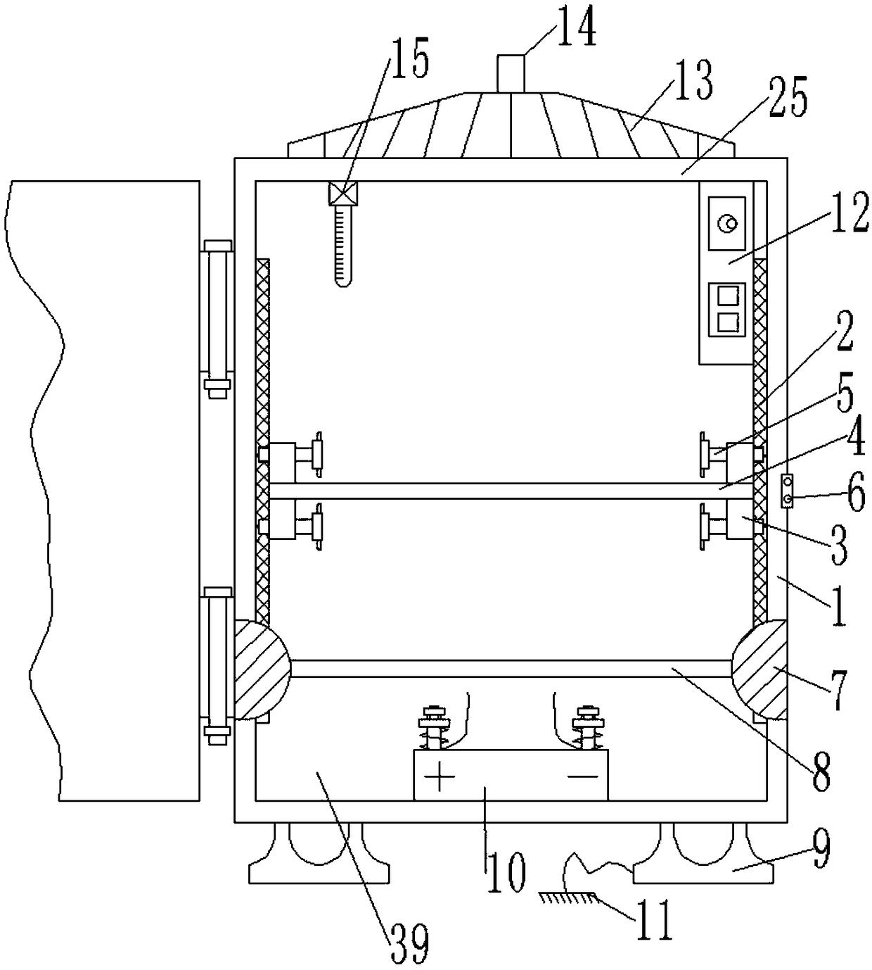
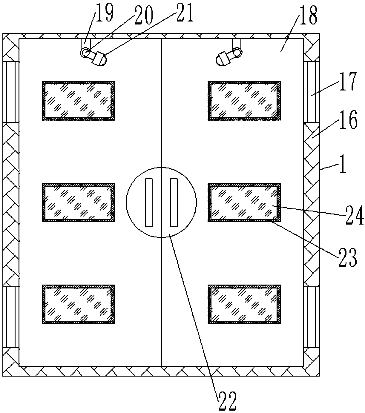
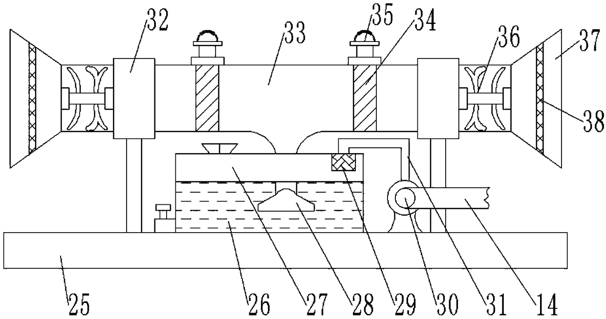
[0027] refer to Figure 1-5 , a power and electrical distribution cabinet for mines with good dust removal performance, including a power distribution cabinet body 1, sliding guide rails 2 are welded on the inner walls of both sides of the power distribution cabinet body 1, and the outer walls of one side of the two sliding guide rails 2 are welded. Slidingly connected with a sliding seat 3, an installation groove is provided on one side of the outer wall of the sliding seat 3, and a storage board 4 is clamped on the inner wall of the installation groove, and the storage board is moved by the relative movement of the sliding seat 3 and the sliding guide rail 2. 4 to ...


PUM


Abstract

The invention relates to a mine electric power electrical distribution cabinet with good dust removal performance, belonging to the technical field of electrical equipment. Aiming at the problems of simple structure design, single function, poor dust-proof effect and inconvenient use of distribution cabinets, the mine electric power electrical distribution cabinet with good dust removal performance is provided. The mine electric power electrical distribution cabinet with good dust removal performance comprises an distribution cabinet body; the inner walls of both sides of the distribution cabinet body are welded with sliding guide rails; sliding seats are connected on the outer walls of one side of the two sliding guide rails in a sliding manner; the outer wall of one side of the sliding seat is provided with an installation groove, and the inner wall of the installation groove is clamped with a storage plate; and the outer wall of one side of the sliding seat is provided with a threaded hole, and the inner wall of the threaded hole is connected with a positioning bolt through the thread. The invention can perform dynamical balance control of the temperature inside the distributioncabinet, therefore, the service performance of the distribution cabinet is ensured; and the invention can adjust the storage space inside the distribution cabinet, thereby effectively arranging the electronic components, therefore, the smoke and dust pollution to the distribution cabinet caused by the environment around the mine is avoided.

Description

technical field [0001] The invention relates to the technical field of electrical equipment, in particular to a power distribution cabinet for mines with good dust removal performance. Background technique [0002] At present, power distribution cabinets are divided into power distribution cabinets, lighting distribution cabinets, and metering cabinets, which are the final equipment of the power distribution system. The power distribution cabinet is a general term for the motor control center. The power distribution cabinet is used in the occasions where the load is relatively scattered and there are few circuits; the motor control center is used in the occasions where the load is concentrated and there are many circuits. They distribute the electric energy of a certain circuit of the upper-level power distribution equipment to the nearest load. This level of equipment shall provide protection, monitoring and control of the load. [0003] After retrieval, the Chinese pate...

Claims


Application Information

Patent Timeline
Patent Type & Authority Applications(China)
IPC IPC(8): H02B1/30H02B1/34H02B1/56
CPCH02B1/30H02B1/303H02B1/306H02B1/34H02B1/565
Inventor 陈现章
Owner 肇庆中能创智信息科技有限公司
Why Eureka
Eureka Blog
Learn More