
Steel rail clamping device

A clamping device, rail technology, applied to rail joints, tracks, laying tracks, etc.

Inactive Publication Date: 2003-08-27
ROBEL BAHNBAUMASCH
View PDF4 Cites 0 Cited by
  • Summary
  • Abstract
  • Description
  • Claims
  • Application Information

AI Technical Summary

Problems solved by technology

A disadvantage of this clamping device is that the two rail clamps must be bolted together before each pull on the rail

Method used


Image

  • Steel rail clamping device
  • Steel rail clamping device

Examples


Embodiment Construction

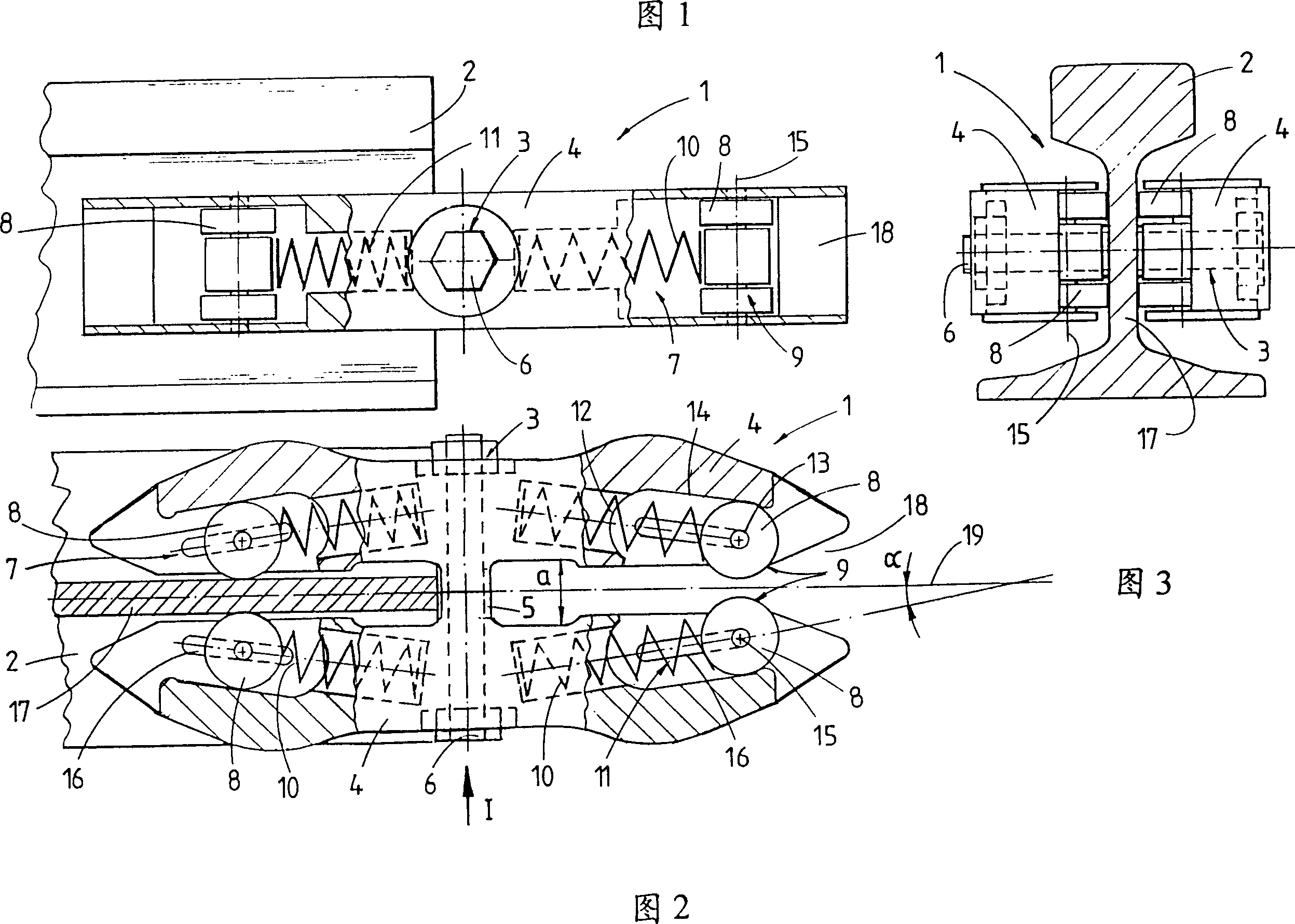
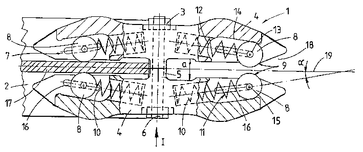
[0015] The rail clamping device 1 shown in FIGS. 1 to 3 for the robust connection of two rails 2 (the second rail is not shown for the sake of clarity) consists of two rail clamping plates 4 which are bolted together. The clamping plates are in contact with each other via a cylindrical partition 5 surrounding the bolts 6 of the bolted connection 3 .

[0016] The end of each rail clamping plate 4 has a clamping wheel opening 7 for placing a clamping part 9 in the form of a clamping wheel 8 . Each clamping wheel 8 can move from the first stopper 12 closer to the bolt 6 in the clamping wheel opening 7 to the second stopper farther away from the bolt 6 under the action of the pressure medium 11 in the form of a helical spring 10. Block 13 moves.

[0017] The contact surface 14 of the clamping wheel opening 7 connecting the two stops 12 , 13 is inclined at an angle α with respect to the longitudinal direction of the bolt 6 for guiding and bearing the clamping wheel 8 . The angle ...


PUM


Abstract

The device (1) connects two rails (2) using two fish plates (4) held at fixed relative distance (a) by a bolt connection (3). Each fish plate has associated clamp elements (9), held in a roller aperture (7). Each element is moved by a pressure medium (11) from a first stop (12) nearer the bolt (6), to a second stop (13) away from it. The stops are connected by a contact surface (14) in the aperture to guide and support a clamp element.

Description

technical field [0001] The invention relates to a rail clamping device for strongly connecting two rails together. The clamping device has two rail clamps connected by bolts. The cleats are spaced longitudinally from each other to support the rail waist. To create a strong connection, the clamping plates are equipped with clamping elements that fit into the openings of the clamping wheels. Background technique [0002] Patent DE 94 08 678 U1 discloses such a rail clamping device. Among them, the clamping part is an eccentrically mounted clamping wheel. When the rails are pulled in the longitudinal direction, a strong connection is automatically created between the clamping wheel and the webs of the two rails. A disadvantage of this type of clamping device is that the two rail clamps must be bolted together before each pull on the rail. [0003] A known rail clamping device from DE 1 784 149 has two curved rail clamping plates for prestressing. For a strong connection t...

Claims


Application Information

Patent Timeline
Patent Type & Authority Patents(China)
IPC IPC(8): E01B11/02E01B11/56E01B29/16
CPCE01B29/16E01B11/02
Inventor 赫特伦迪·约瑟夫
Owner ROBEL BAHNBAUMASCH
Learn More