
Power electrical transformer with self-cooling function

A technology of electric power and transformers, which is applied in the field of transformers, can solve the problems of closed protection in the normal temperature state when the voltage cannot be transformed, and achieve the effect of avoiding the use of electricity

Active Publication Date: 2020-12-04
莱芜鲁能开源集团电器有限公司
View PDF7 Cites 0 Cited by
  • Summary
  • Abstract
  • Description
  • Claims
  • Application Information

AI Technical Summary

Problems solved by technology

However, this equipment cannot provide outdoor sealing protection for the transformer and normal temperature state, and can effectively cool down when the temperature is high.

Method used


Image

  • Power electrical transformer with self-cooling function
  • Power electrical transformer with self-cooling function
  • Power electrical transformer with self-cooling function

Examples


specific Embodiment approach 1

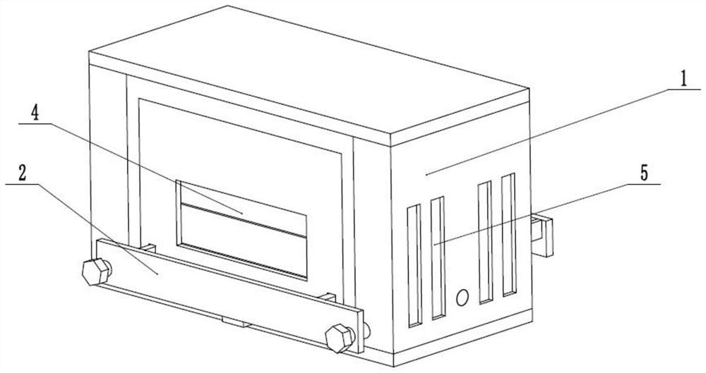
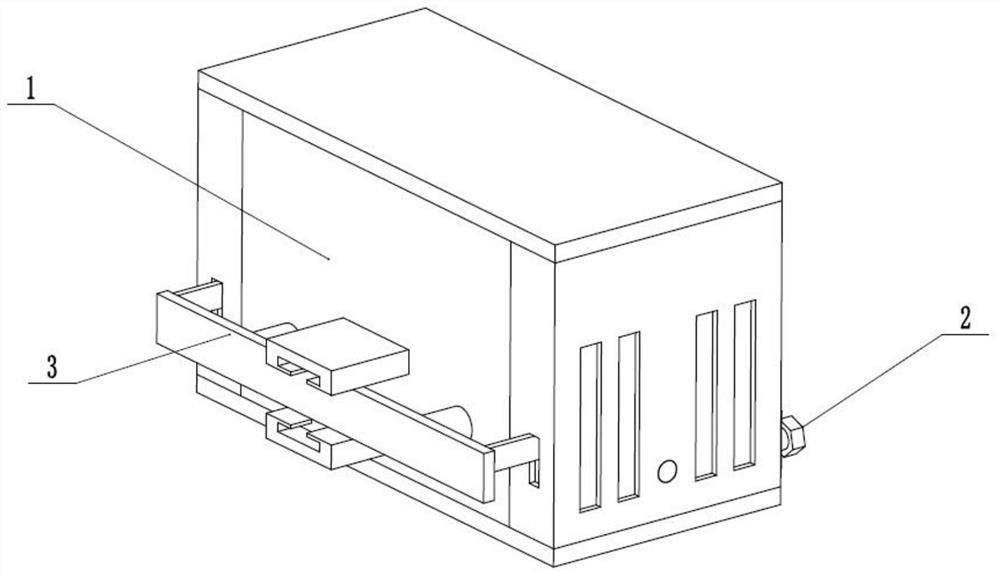
[0031] Such as Figure 1 to Figure 11As shown, a power electrical transformer with a self-cooling function includes a transformer outdoor closed protection frame 1, an adjustable transformer load fixing seat 2, a self-adjusting driver 3, a self-adjusting sliding front door 4, multiple ventilation side doors 5 and compressed air Expander 6, the adjustable transformer load fixing seat 2 is connected to the rear end of the transformer outdoor closed protection frame 1 through thread fit, and the front end of the adjustable transformer load fixing seat 2 is attached to the self-adjusting driver 3, The self-adjusting driver 3 and the self-adjusting sliding front door 4 are meshed and driven, and the self-adjusting sliding front door 4 is rotatably connected in the outdoor closed protection frame 1 of the transformer. Respectively hinged on the two ends of the inner wall of the closed protection frame 1 outside the transformer, the compressed air expander 6 is fixedly connected to t...

specific Embodiment approach 2

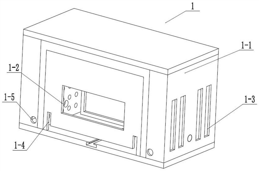
[0033] Such as Figure 1 to Figure 11 As shown, this embodiment will further explain Embodiment 1. The outdoor closed protective frame 1 of the transformer includes a protective box 1-1, a front ventilation slot 1-2, a plurality of side ventilation slots 1-3, and an adjustment slot 1 -4. Two rotating round holes 1-5, two inner wall interval ventilation plates 1-6, T-shaped chute 1-7 under the inner wall, two front sliding seats 1-8 and two limiting rack chute 1 -9, the center of the rear end of the protection box 1-1 is provided with a connected front ventilation slot 1-2, and the two ends of the protection box 1-1 are respectively provided with a plurality of connected side ventilation slots 1-3, the protection box The lower side of the rear end of 1-1 is provided with a connected adjustment slot 1-4, two rotating round holes 1-5 are evenly arranged on the rear end of the protection box 1-1, and the ventilation plates 1-6 are evenly spaced between the two inner walls. Fixedl...

specific Embodiment approach 3

[0035] Such as Figure 1 to Figure 11 As shown, this embodiment will further explain Embodiment 2. The adjustable transformer load fixing seat 2 includes a transformer 2-1, a transformer load slide base 2-2, an adjustment connecting plate 2-3 and two adjustment Bolt 2-4, the lower end of the transformer 2-1 is fixedly connected to the transformer load slide 2-2 by bolts, the transformer load slide 2-2 is slidably connected in the adjustment slot 1-4, and the adjustment connection plate 2- 3. It is fixedly connected to the rear end of the transformer bearing slide seat 2-2. The two adjusting bolts 2-4 are respectively connected to the adjusting connecting plate 2-3 through thread fit, and the two adjusting bolts 2-4 are respectively connected to the two Rotate in the circular hole 1-5. The transformer 2-1 is fixedly connected to the transformer bearing slide 2-2 by bolts; when the temperature of the transformer 2-1 rises, the temperature of the compressed air in the compressed...


PUM


Abstract

The invention relates to the field of transformers, in particular to a power electrical transformer with a self-cooling function. The transformer comprises a transformer outdoor closed protection frame, an adjustable transformer on-load fixing base, a self-adjusting driver, a self-adjusting sliding front door, a plurality of ventilation side doors and a compressed air expansion expansion device, the adjustable transformer on-load fixing base is connected to the rear end of the transformer outdoor closed protection frame in a threaded fit mode, the front end of the adjustable transformer on-load fixing base is attached to the self-adjusting driver, the self-adjusting driver is in meshing transmission with the self-adjusting sliding front door, and the self-adjusting sliding front door is rotationally connected into the transformer outdoor closed protection frame. The transformer has the beneficial effects that when the transformer works and the temperature is high, a closed protection shell is automatically opened for ventilation, and when the transformer does not work and the temperature is normal, the closed protection shell carries out effective closed protection on the transformer located outdoors.

Description

technical field [0001] The invention relates to the field of transformers, in particular to a power electric transformer with self-cooling function. Background technique [0002] The patent number is CN201910381618.X, which discloses a power transformer with self-cooling function, including a box, and a partition is fixed inside the box, and the partition divides the box into a working room and a cooling room. A transformer body is fixed indoors, a temperature sensor is arranged on the top of the transformer body, a servo motor is fixed in the cooling chamber, the output shaft of the servo motor is fixed with a screw rod, and a drive nut is threadedly connected to the screw rod, The drive nut is inlaid on the push plate, and push rods are fixed on both sides of the push plate, and a baffle is fixed on the end of the push rod, and a number of cooling holes are arranged on the baffle, and the baffle and the The side ends of the box body are in close contact, heat dissipation ...

Claims


Application Information

Patent Timeline
IPC IPC(8): H01F27/02H01F27/06H01F27/08
CPCH01F27/02H01F27/025H01F27/06H01F27/085
Inventor 陈远旭
Owner 莱芜鲁能开源集团电器有限公司
Features
  • Generate Ideas
  • Intellectual Property
  • Life Sciences
  • Materials
  • Tech Scout
  • Unparalleled Data Quality
  • Higher Quality Content
  • 60% Fewer Hallucinations
Learn More